Addressable LEDs (ALED)
Addressable LEDs are in my opinion the coolest feature you can add to a Virtual Pinball setup. They are bright, colourful and can be combined to create shapes and text. Setting it up is not that difficult if you follow the following steps.
🎬 Video Tutorial: Watch on YouTube
---What is the Required Hardware?
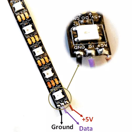
You will need a Addressable LED ( ALED ) WS2812B. Those comes in different forms, Strips, Rings, Matrix, Individual LED and Buttons. Check your specs, but most ALED needs to be powered by a 5V power supply.
Use a separate power supply to power up your ALED. If you want 2 side strips, a DOT matrix and speaker rings, you will end up using around 600 ALED. The power consumption is 60mA per pixel. 600×60mA = 36 Amps. Get a 60 Amp power supply for your ALED.
The Ground will connect to the negative terminal of your power supply, the 5+V to the Positive terminal of your power supply and the Data will go on the ALED controller board.
ALED controller board
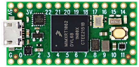
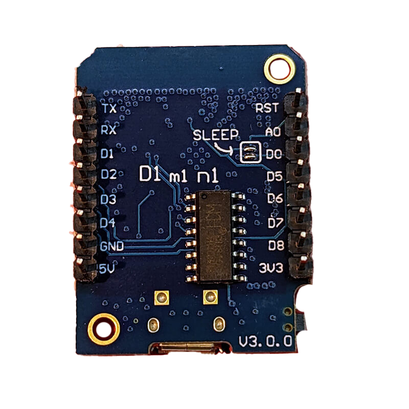
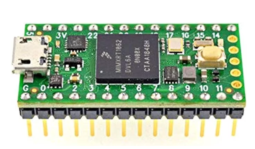
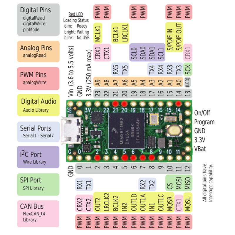
I am recommending 2 types of controller boards the TEENSY 4.0 or the WEMOS D1 MINI. The 2 boards are almost identical in terms of performance. The Wemos is a lot cheaper.
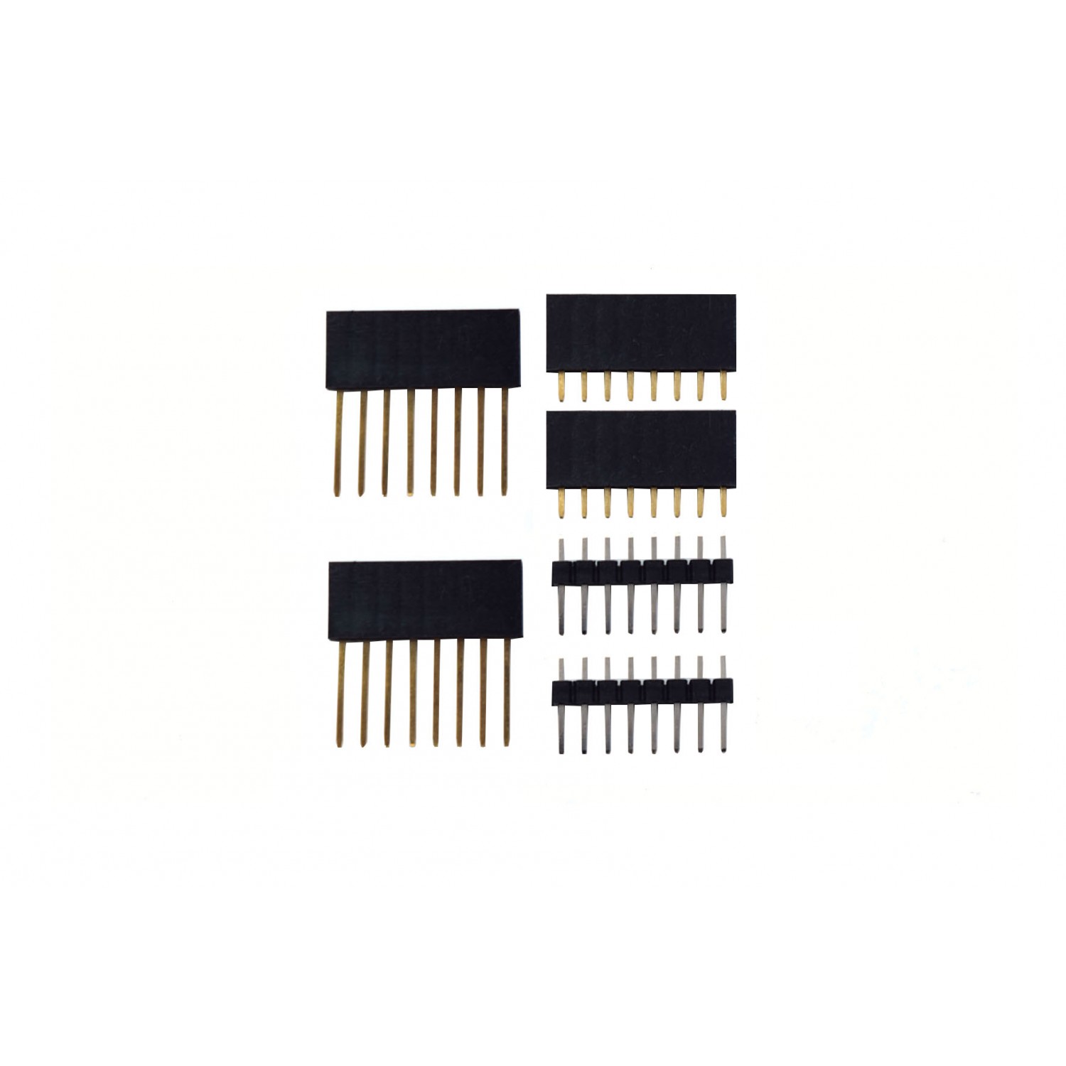
If you pick any of the 2 boards you will need to solder the header pins 0.1 pitch. If you are not familiar with soldering, you can buy a board with pre-soldered Header Pins. You can look up the links in the Parts section.
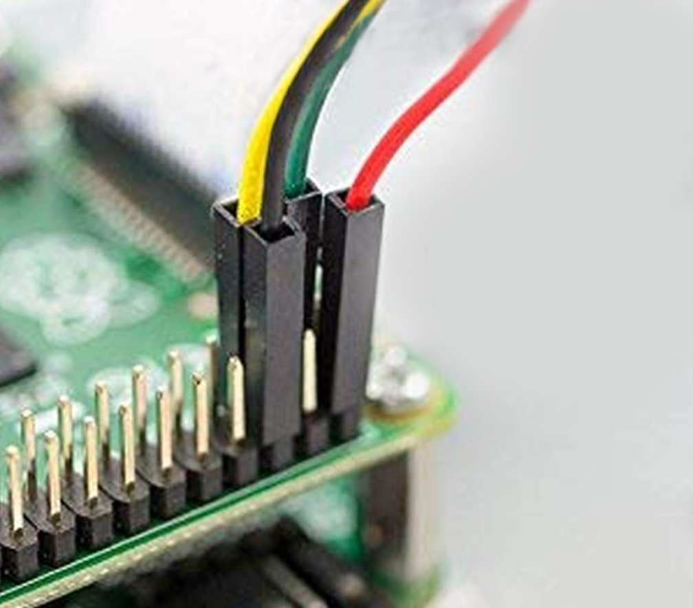
Connect a dupont cable to the pins of the Wemos or Teensy to the signal pin on the addressable LED.
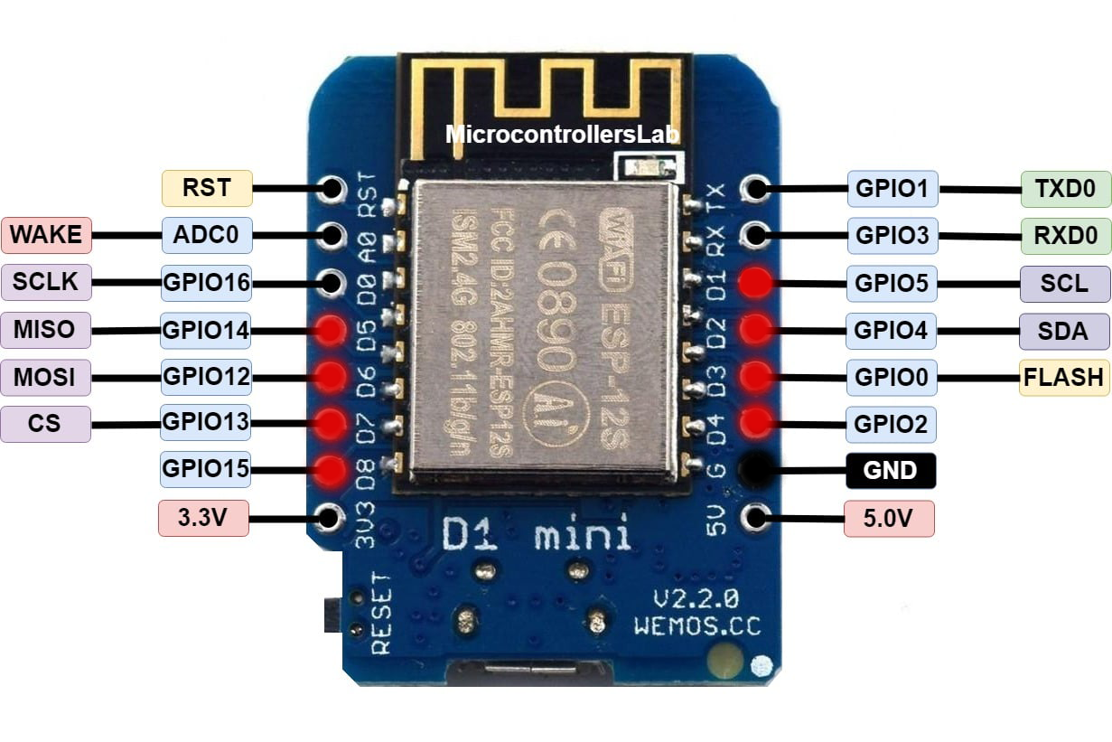
You will connect the Addressable LED pins to the WEMOS RED ports from D1 to D8. And the GND will connect to your common ground terminal. The 5V and 3.3V out, we are not going to connect. The WEMOS gets the required power from the USB connection.
For the Teensy 4.0: connect ALED pins to RED ports 2-5-6-7-8-15-20-21. GND connects to your common ground terminal. Do not connect 5V or 3.3V — Teensy is powered by USB.
Spend a Few $$ to Make Your Life Easier
There are adapters for both the Teensy and WEMOS which makes connections a lot easier. You can find all Hardware links in the Parts Section.
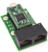
Teensy 3.2–4.1 Octo2811 Adapter
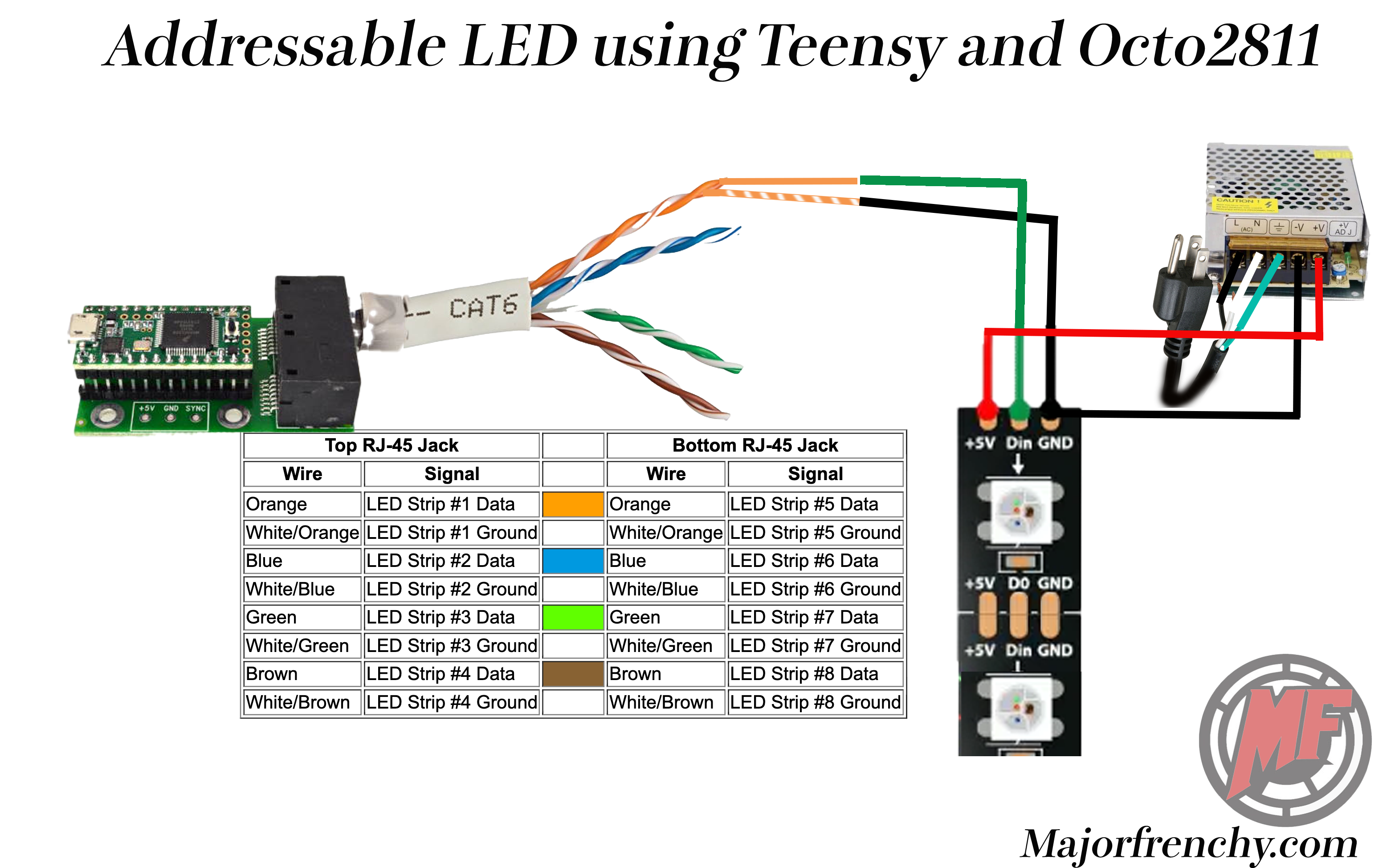
Using the Octo2811 adapter will allow you to connect the Addressable LED by using RJ45 Cat5 or Cat6 cables. The Octo2811 is acting as a "dock" and you simply insert the pins soldered on the Teensy to the Octo2811.
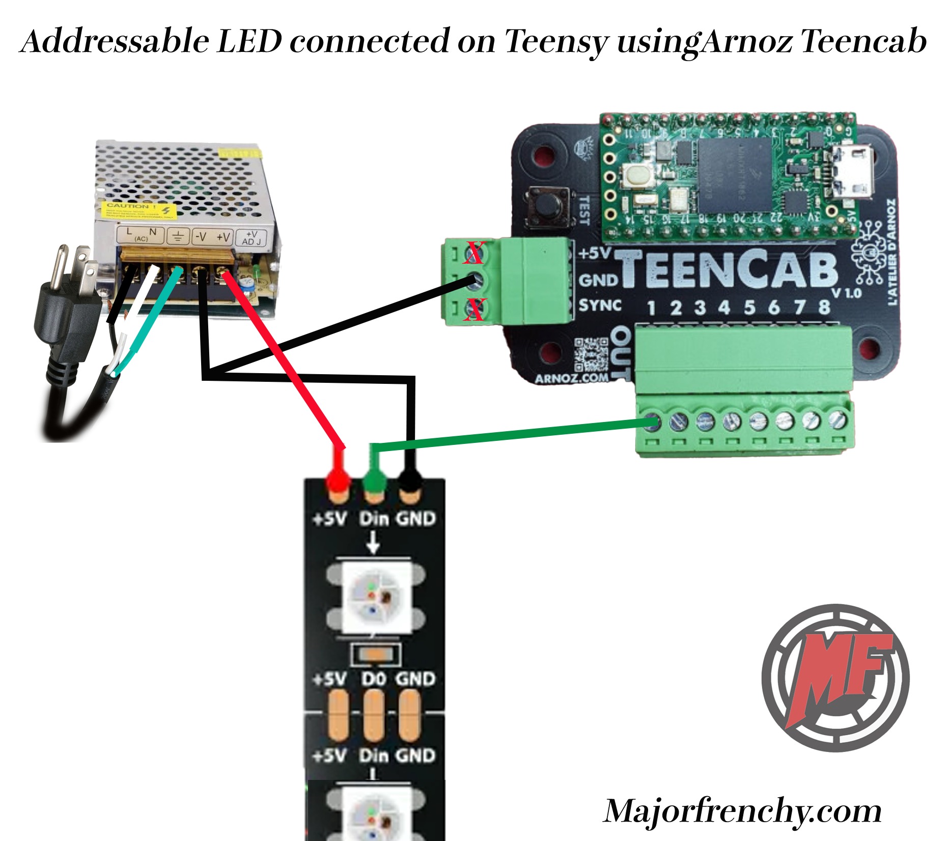
Teensy 3.2–4.1 Arnoz Teencab Adapter
Simplifies all Teensy connections into a clean plug-and-play board.
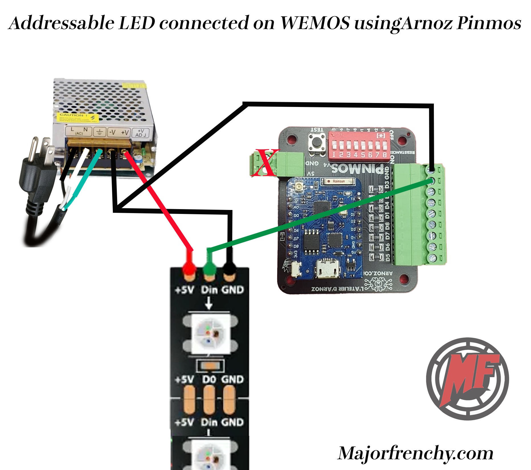
Wemos D1 Mini Arnoz PINMOS Adapter
Same idea for the Wemos. I am currently using this in my cabinet — makes things a lot simpler.
You connect each strip to a different port. For example:
- Left strip → Port 1
- Right strip → Port 2
- Matrix → Port 3
- Left and right speaker rings → Port 4
- Undercab → Port 5
- Any other ALED → Ports 6–7–8
Everything is Connected — Now What?
Once all your strips are connected, you will need to configure the software and flash the firmware. (If you purchased from Arnoz, it is already flashed and ready to go.)

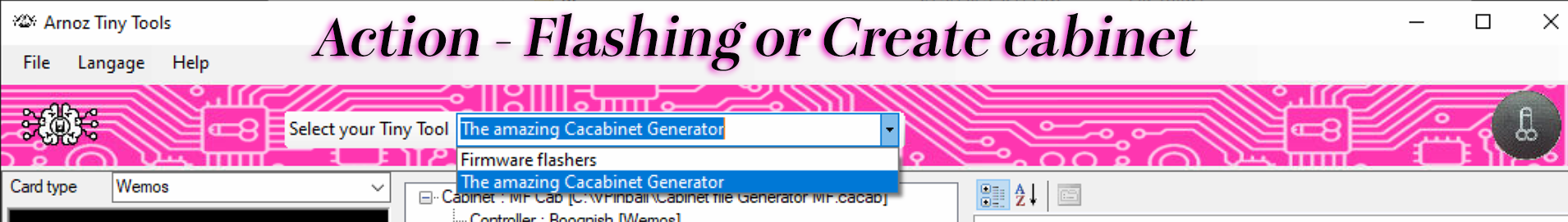
You have 2 options: the Firmware Flasher (to flash the Teensy or PINMOS) and the Cabinet Creation tool. The Cabinet file tells DOF how many LEDs you have and what channel they are on.
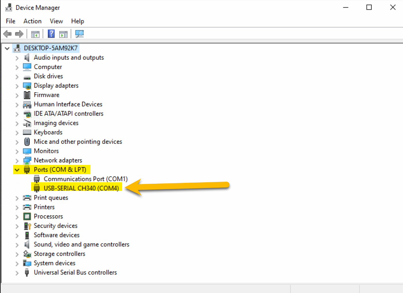
Check your Serial port for the Addressable LED controller. Mine is COM4. Check your own port for the USB-SERIAL in Device Manager.
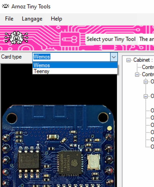
Pick in the Card Type dropdown if you have a Teensy or Wemos.
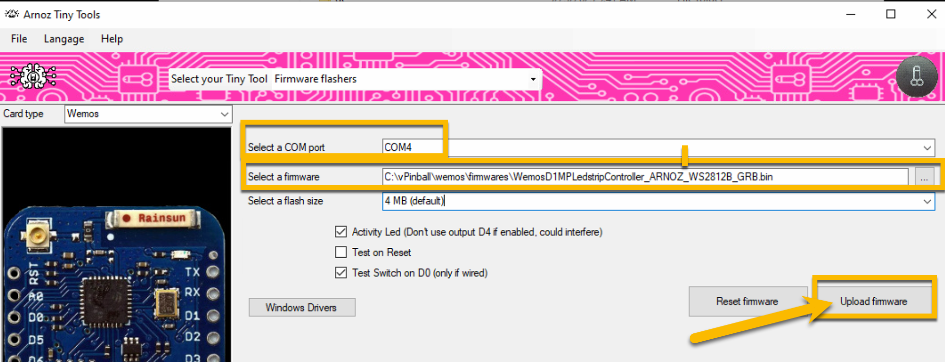
After selecting the type of card, select your COM port and firmware. The firmware is in the TinyTool directory. Pick the Firmware matching the type of ALED you purchased.
Creating the cabinet file is required in order to use Addressable LED. This step has gotten a lot easier thanks to Arnoz and his Tiny Tools. Connect the USB cable of the ALED controller to your PC.
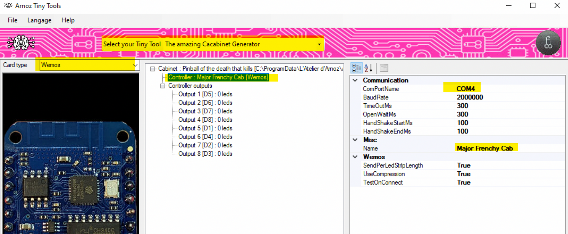
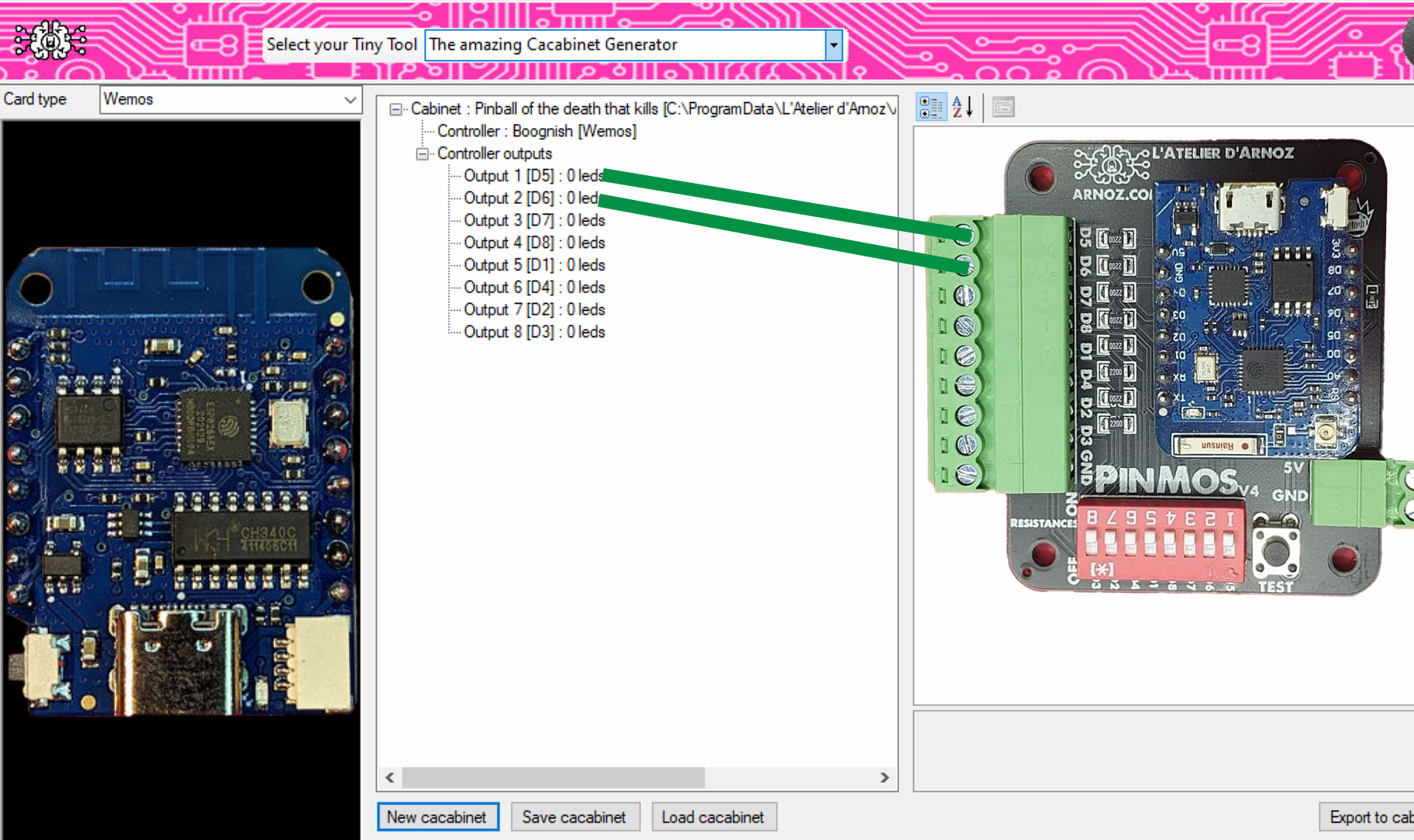
Set the COM Port to your value. You can change the cabinet name to something of your choice.
I connected 2 ALED strips (144/meter): left strip on D5 Port 1 and right strip on D6 Port 2.
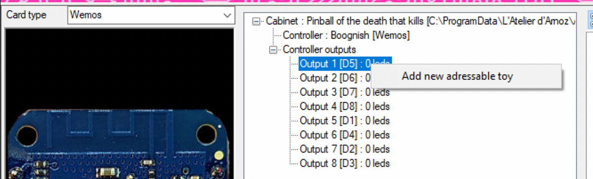
Now you need to set the Addressable LED for port 1. Click it and Add new addressable toy.
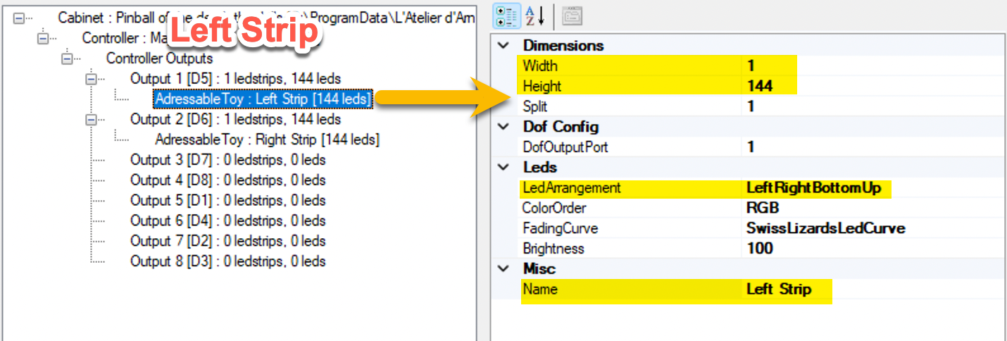
Here you set the length and height of the ALED strip. I have a 144 LED strip (1 width, 144 height).
Set the LED Arrangement to LeftRightBottomUp if your left strip arrows are pointing towards the Backglass.
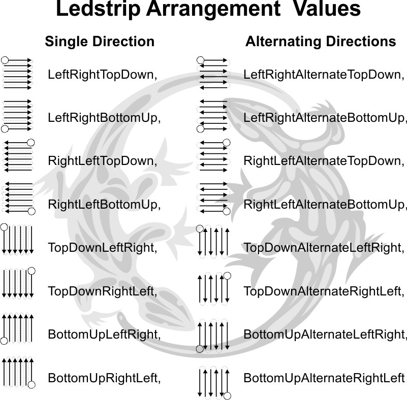
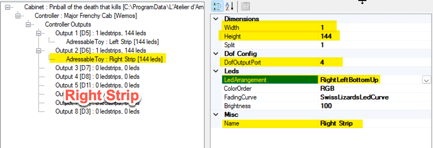
This is the settings for the right playfield strip. The 1st strip uses ports 1-2-3, so the next available port is 4. This strip will use ports 4-5-6. If arrows point towards the Backglass, pick RightLeftBottomUp.
Single Strip / Buttons / DOT Matrix
The next setting is the LED arrangement — this indicates the path the LED is travelling (follow the arrow direction on the strip). The DOF port uses 1 port per colour, 3 colours per strip.
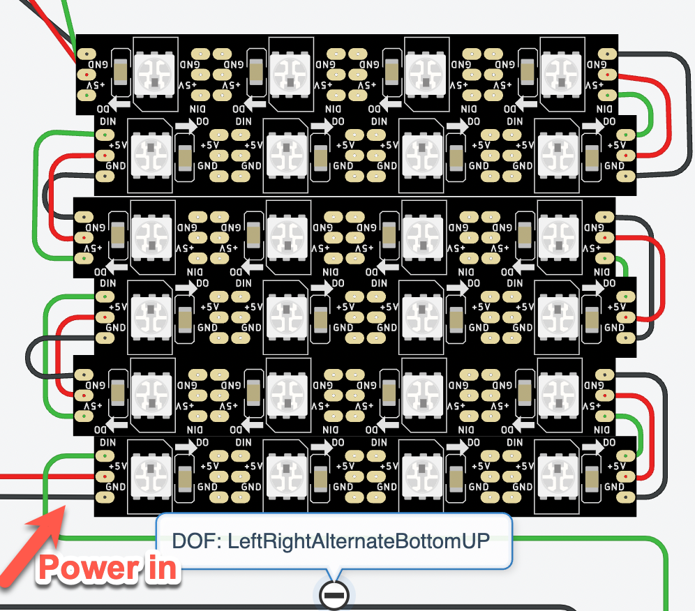
For a DOT matrix: power is injected on the bottom left strip. Arrangement: LeftRightAlternateBottomUp.
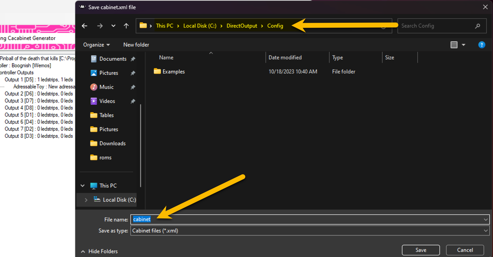
When you are done setting the ALED in the cabinet configurator, name it cabinet and save/export your cabinet file to the DirectOutput/config folder.
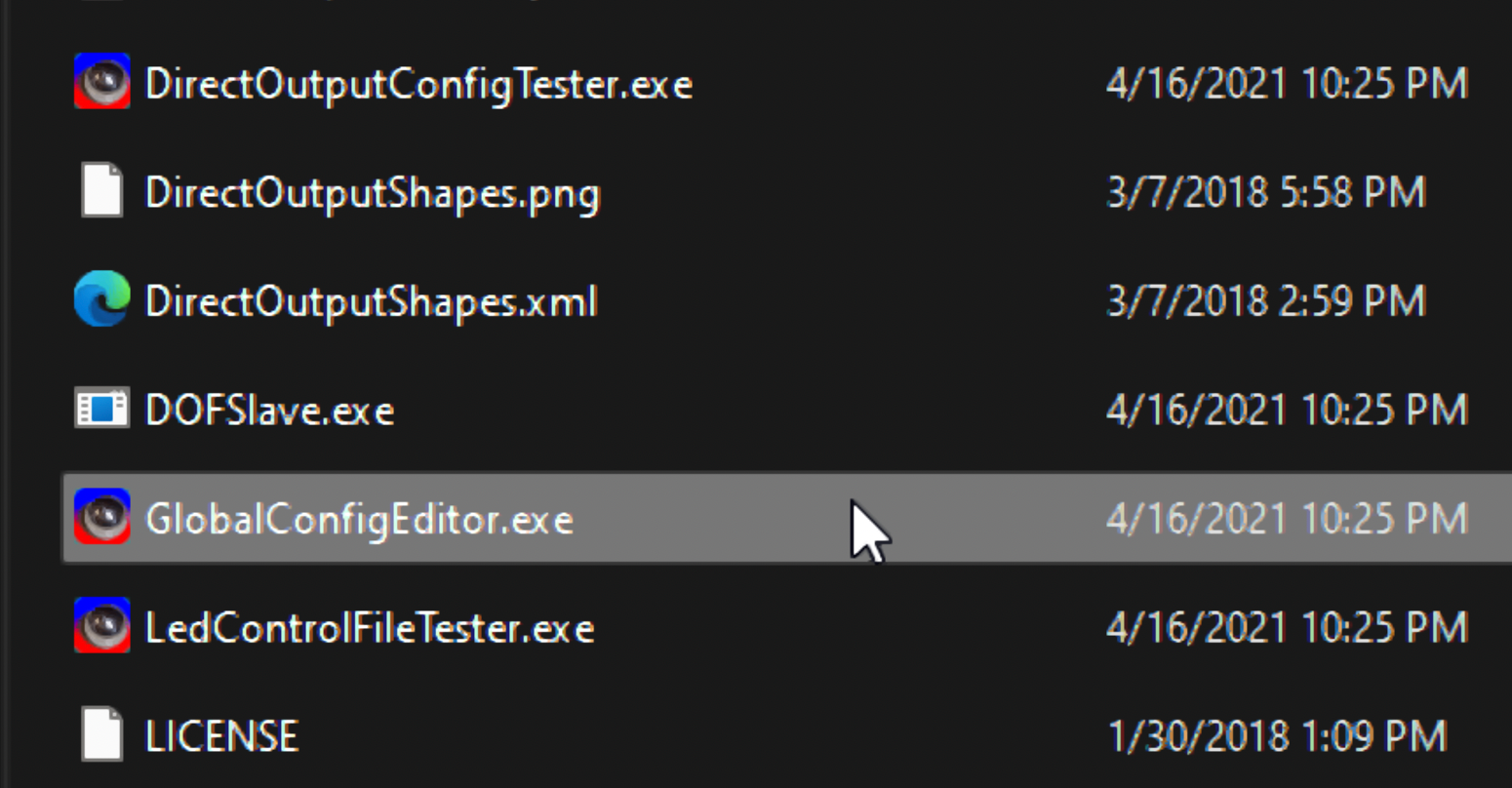
Open GlobalConfigEditor.exe.
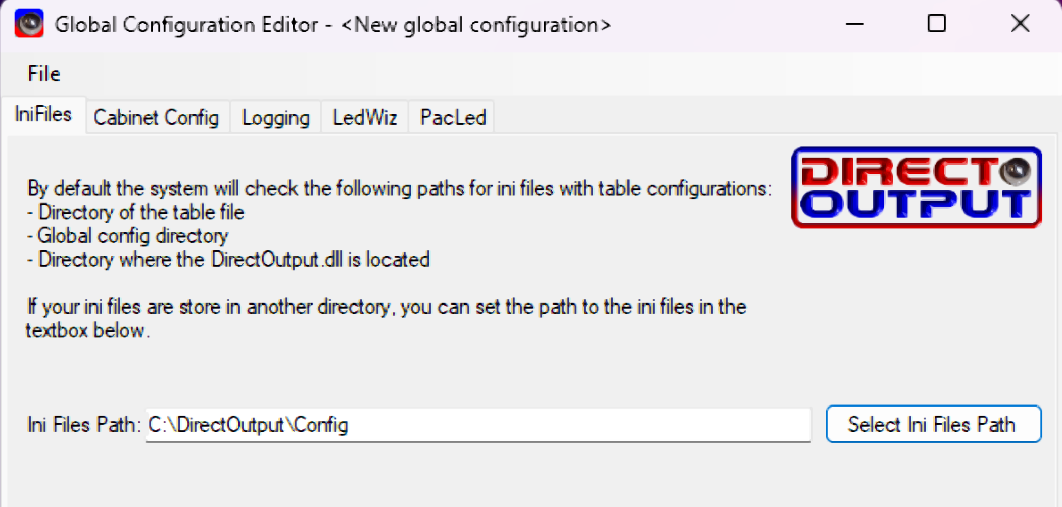
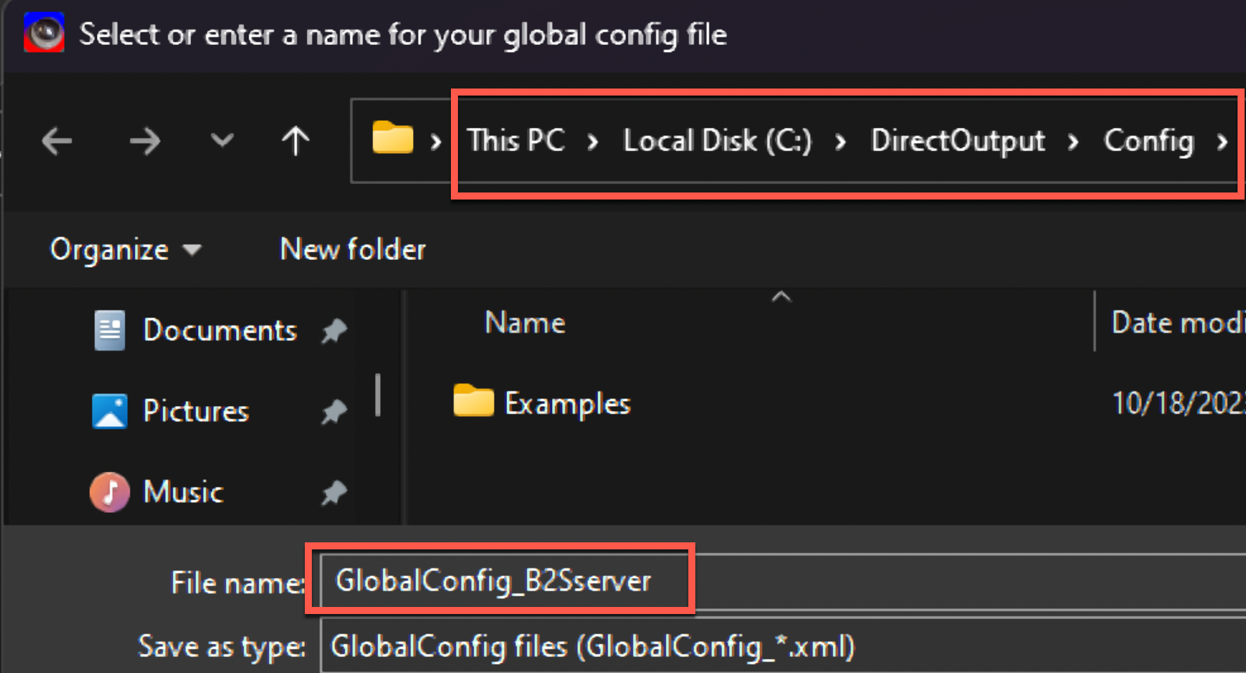
Save as GlobalConfig_B2Sserver.xml in C:\DirectOutput\Config.
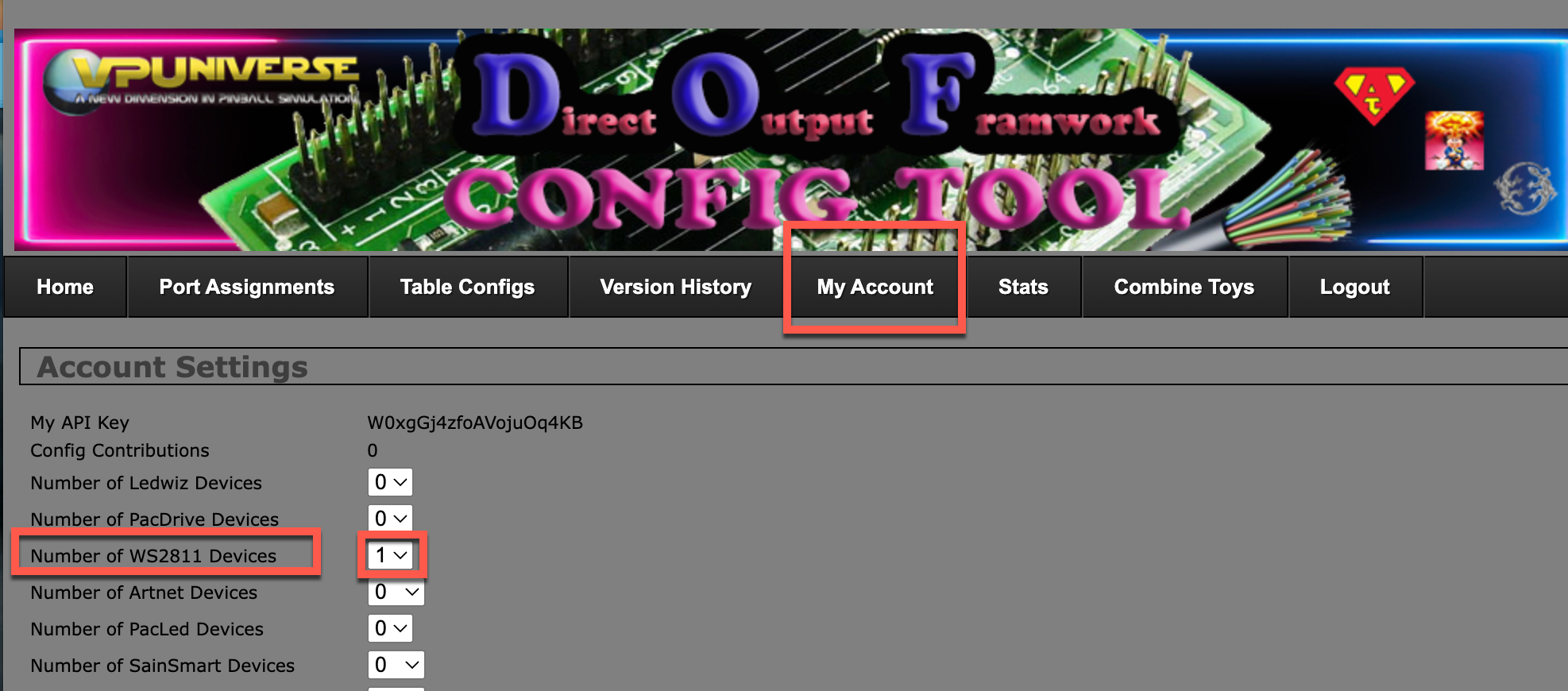
Head over to DOF Config Tool → My Account → add a WS2811 device → Save.
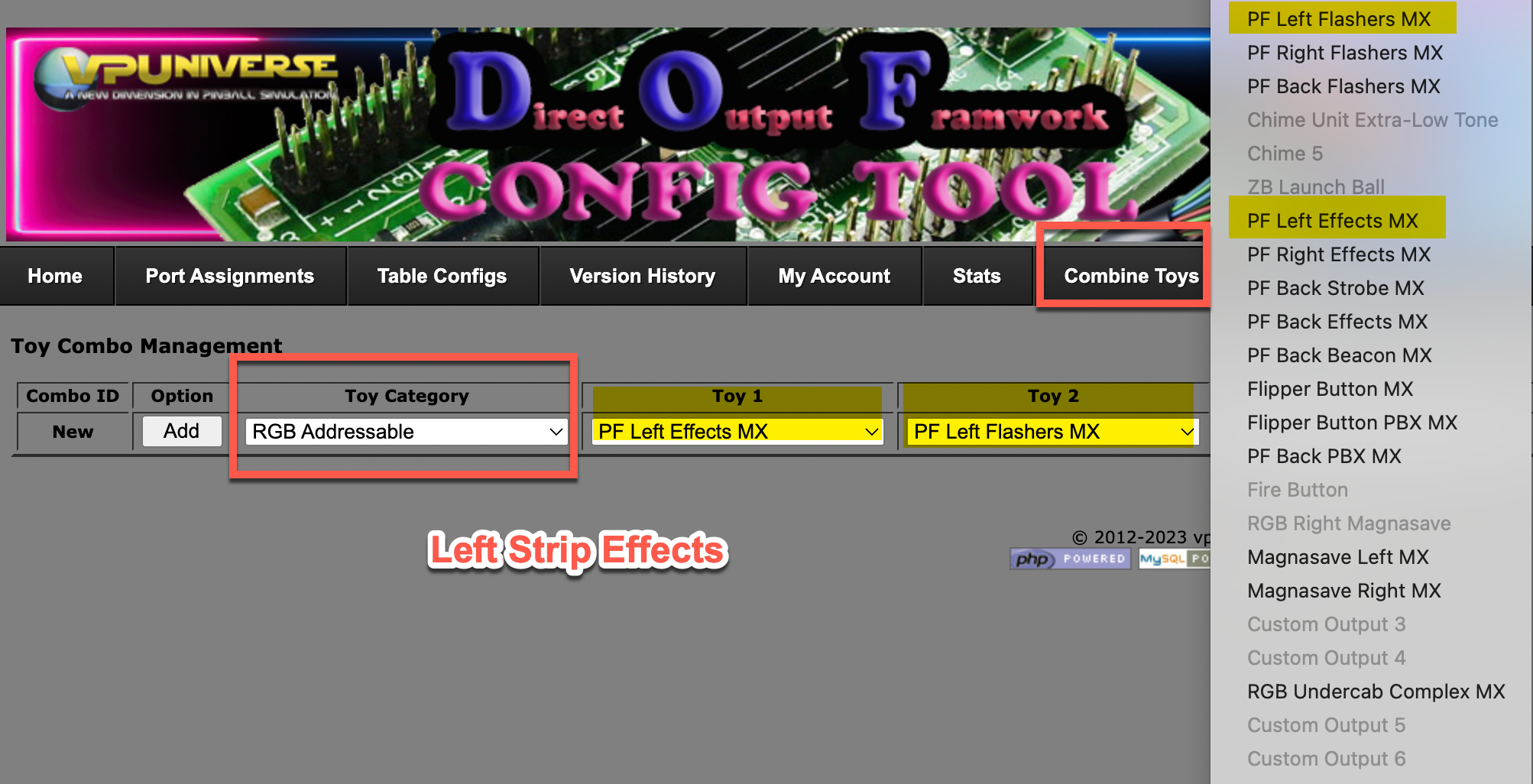
Here in the Combo screen you decide to combine effects for the strip. The basic combo for the side strips is PF Left Effect MX (MX = Addressable LED).
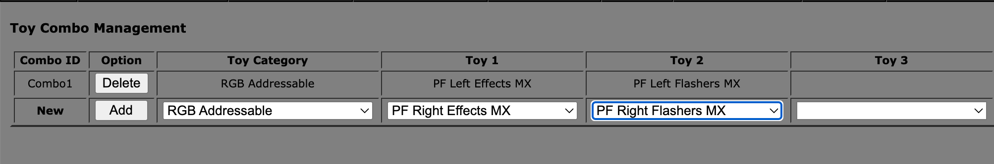
Left strip → PF Left Effect MX
Do the same for the right strip → PF Right Effect MX
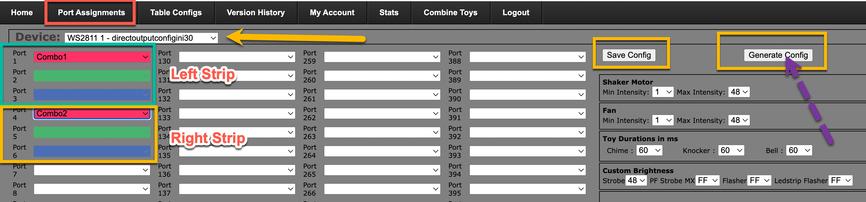
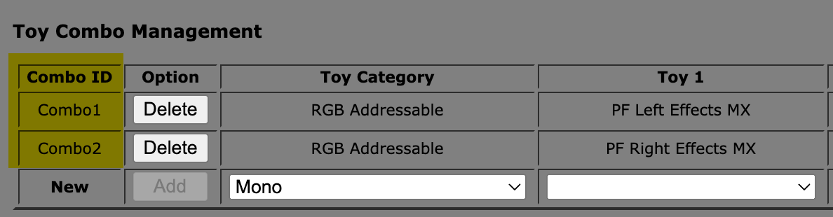
The Left Strip is now called Combo1 and the Right Strip Combo2. Click Port Assignment → select WS2811. The left strip uses ports 1-2-3 and the right strip uses 4-5-6. Selecting Combo1 will automatically pre-fill ports 1-2-3 with the different colours.
Save your config and generate the config file.
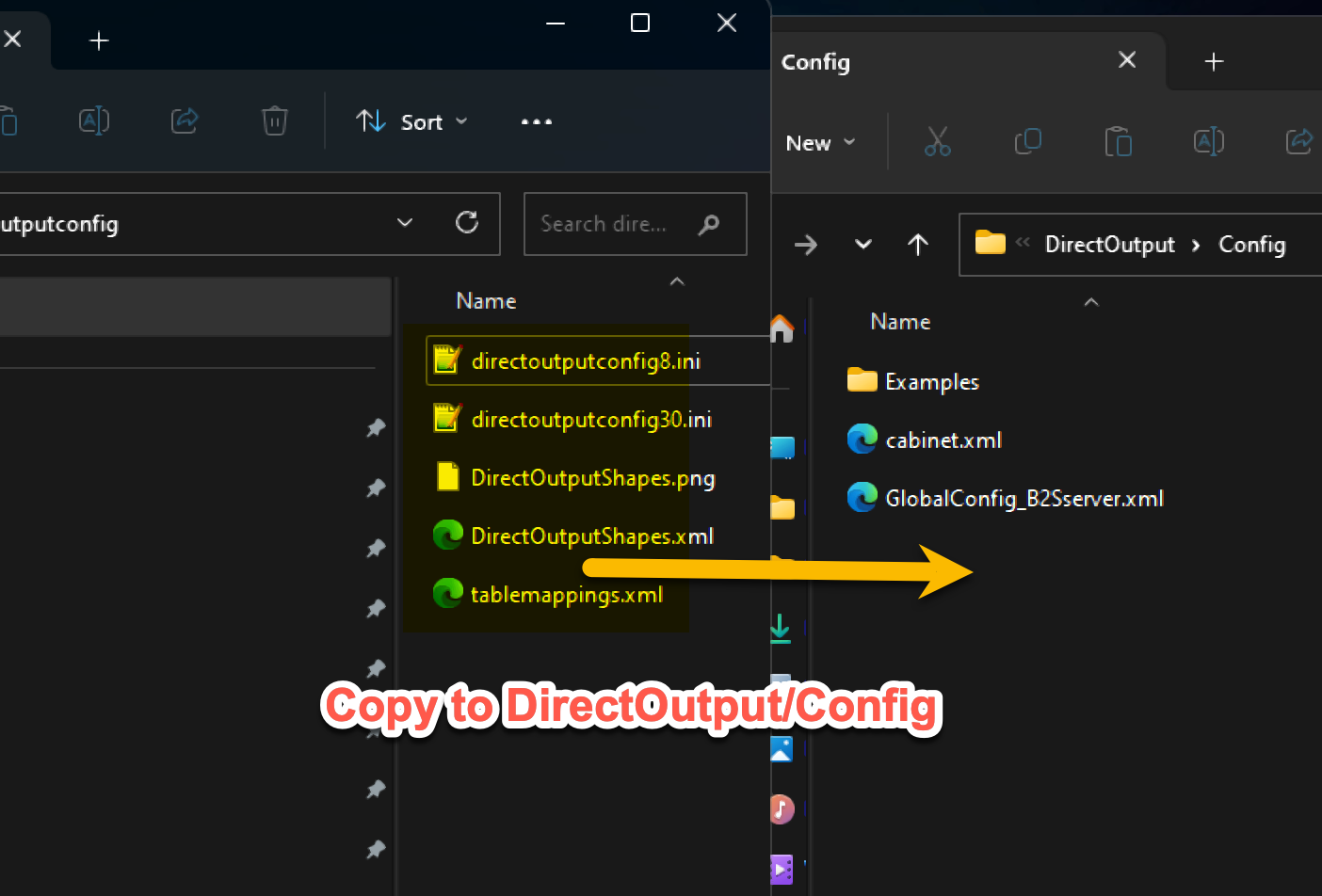
Extract the content of DirectOutput.zip and copy all files to C:\DirectOutput\Config.
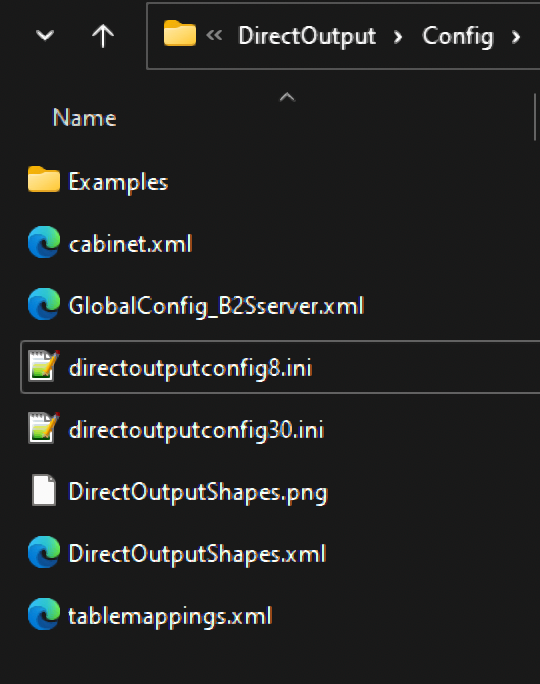
Your folder must look like this for DOF to work with the addressable LED. The directoutputconfig8 and 30.ini filenames may differ based on your controller, but all other files must match.
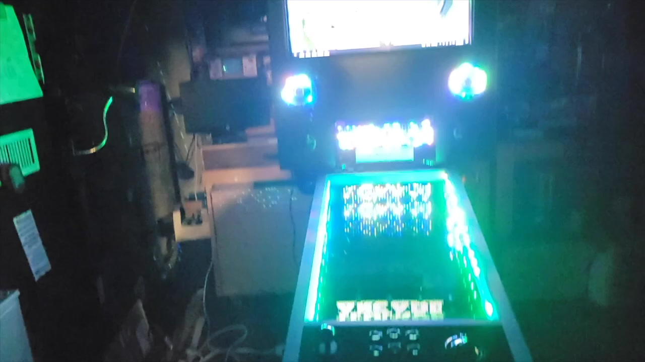
The Result
🔌 Bonus — Wiring Simulator: tinkercad.com/things/3zd2TP7LBEf
---