Cab Building
 I built a full size virtual pinball cabinet and will share my steps. Shout out to Way of the Wrench — I followed his building guide and adapted it to my needs.
**Plans:** [Way of the Wrench cabinet plans (PDF)]
Download File
---
I built a full size virtual pinball cabinet and will share my steps. Shout out to Way of the Wrench — I followed his building guide and adapted it to my needs.
**Plans:** [Way of the Wrench cabinet plans (PDF)]
Download File
---
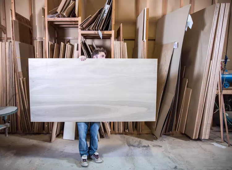
Get Your Wood
I used 3/4" birch plywood, good one side. The one good side plywood is more expensive but saves time on filling and sanding.
I used 3/4" birch plywood, good one side. The one good side plywood is more expensive but saves time on filling and sanding.
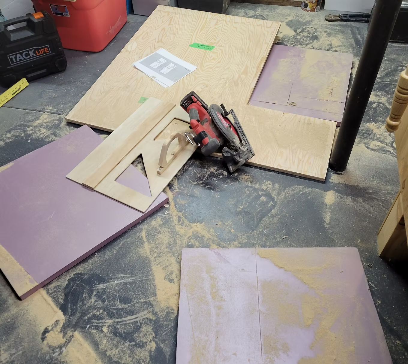
Marking and Cutting
Take extra time to mark your lines and use a guide to ensure accuracy. Cutting your boards on a piece of styrofoam works like a charm.
Take extra time to mark your lines and use a guide to ensure accuracy. Cutting your boards on a piece of styrofoam works like a charm.
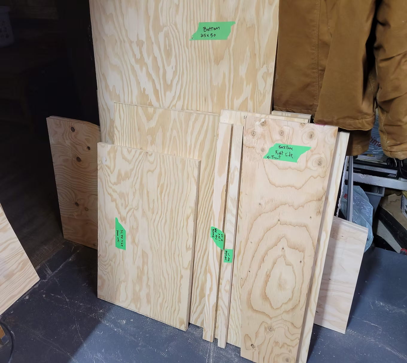
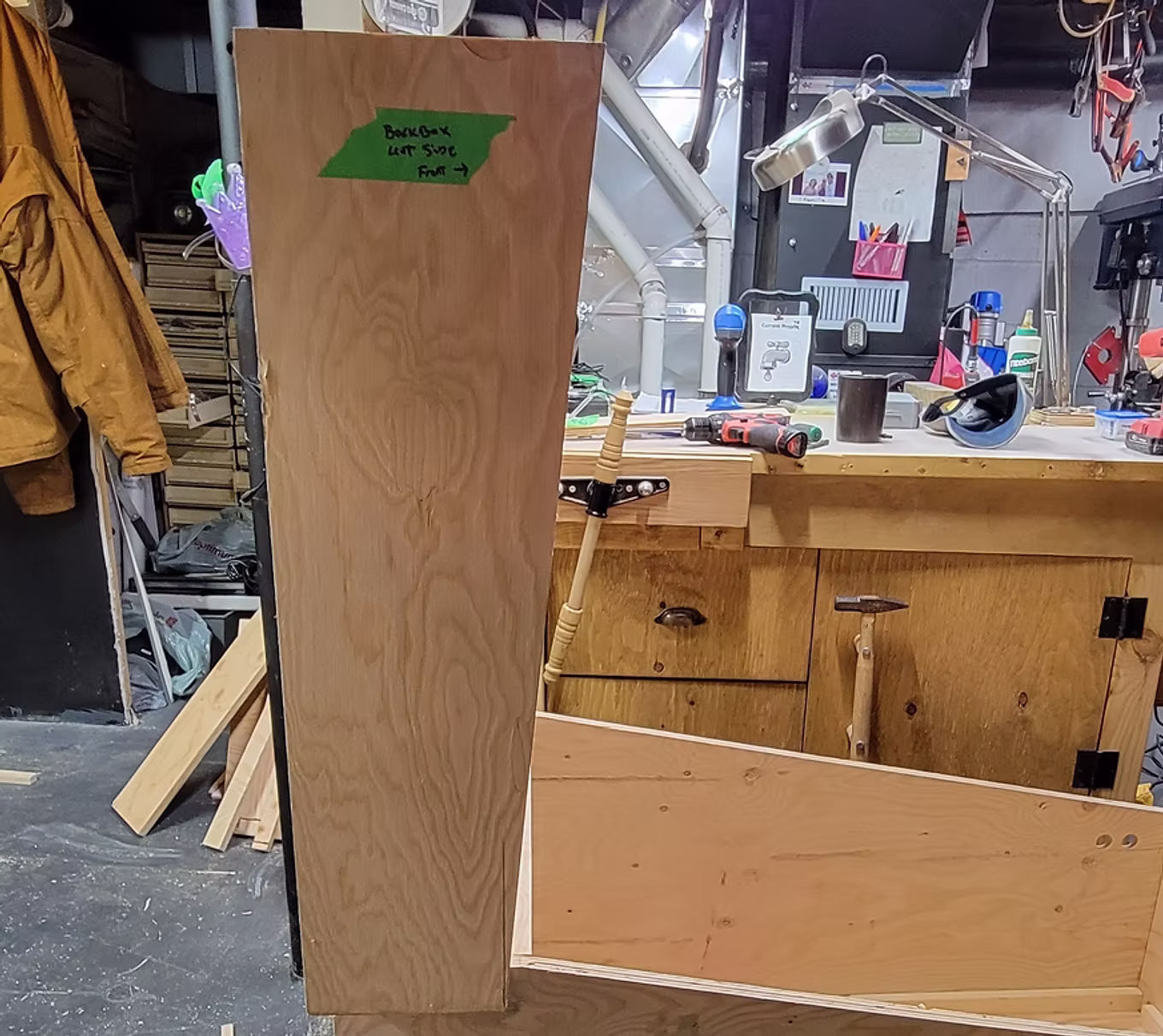
Mark Your Pieces
I used painter tape to mark dimensions and label each piece. This makes assembly much easier.
I used painter tape to mark dimensions and label each piece. This makes assembly much easier.
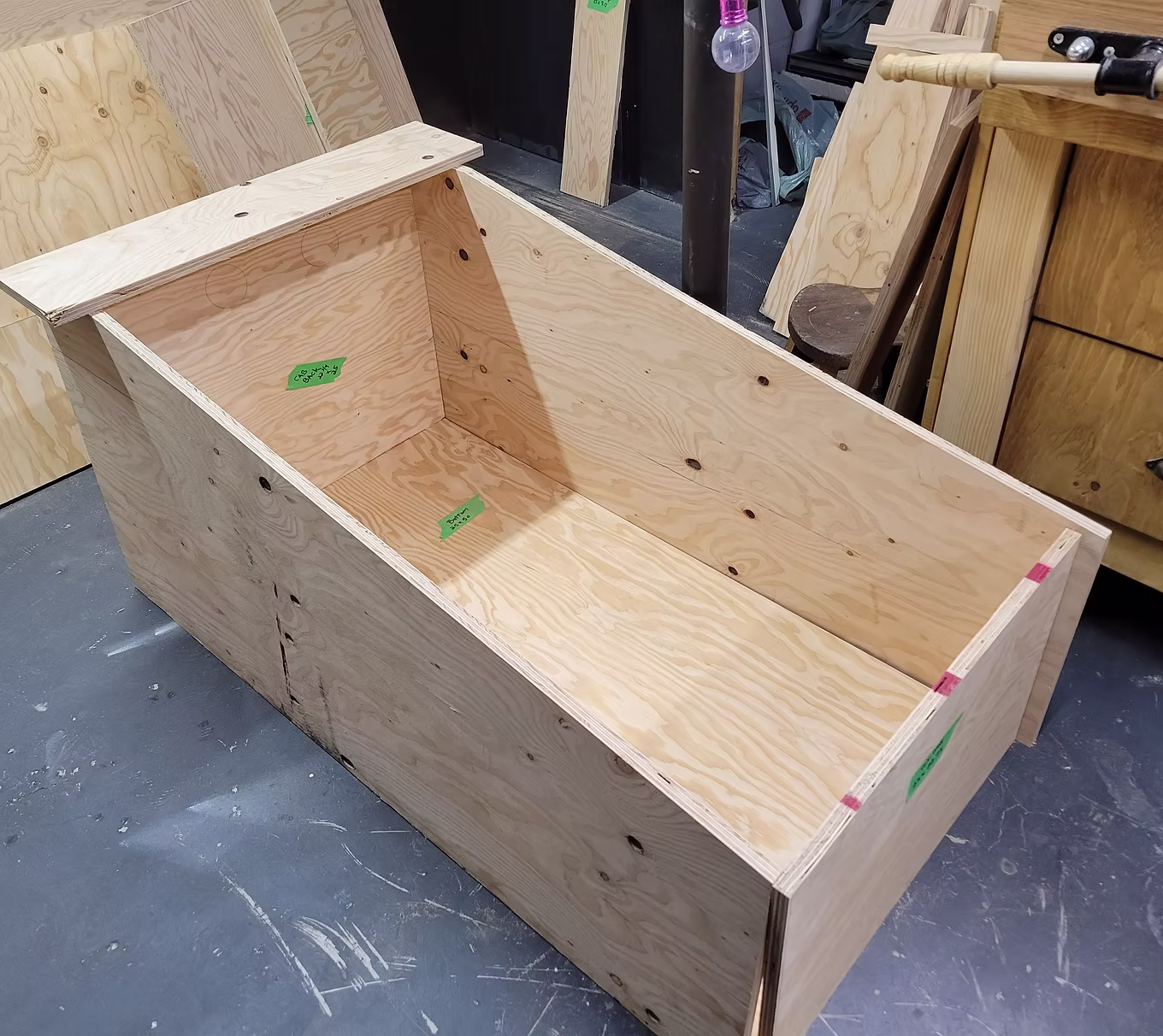
Dry Fitting
It is a lot easier to make adjustments during the dry fitting stage.
It is a lot easier to make adjustments during the dry fitting stage.
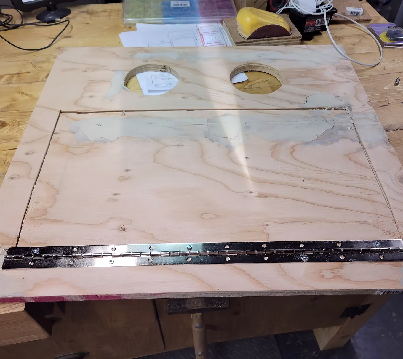
Back Cabinet Panel
I installed a piano hinge and drilled two 4" holes for exhaust fans.
I installed a piano hinge and drilled two 4" holes for exhaust fans.
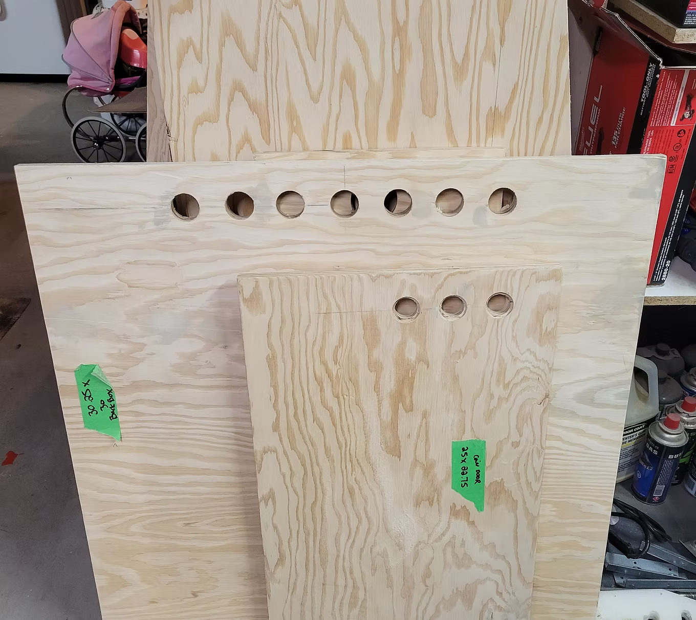
Back Box Vent Holes
Not much heat comes out of the backbox — simple holes at the top drilled with a 1-1/8" Forstner bit are sufficient.
Not much heat comes out of the backbox — simple holes at the top drilled with a 1-1/8" Forstner bit are sufficient.
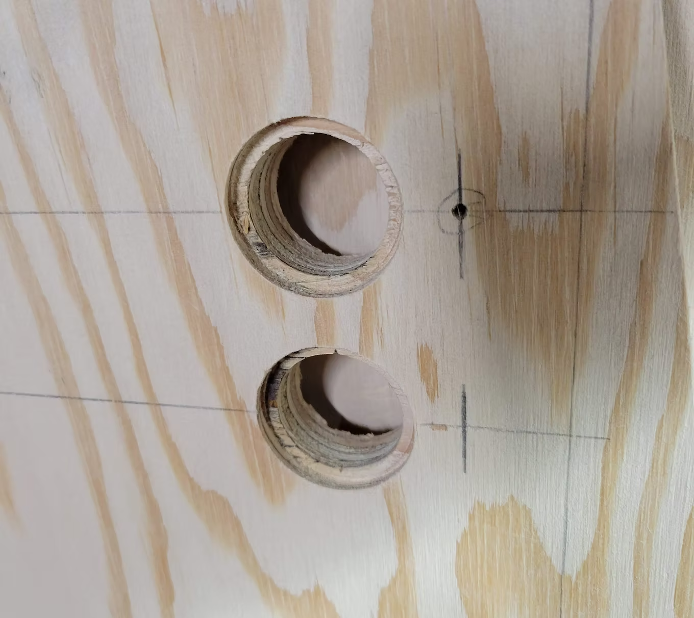
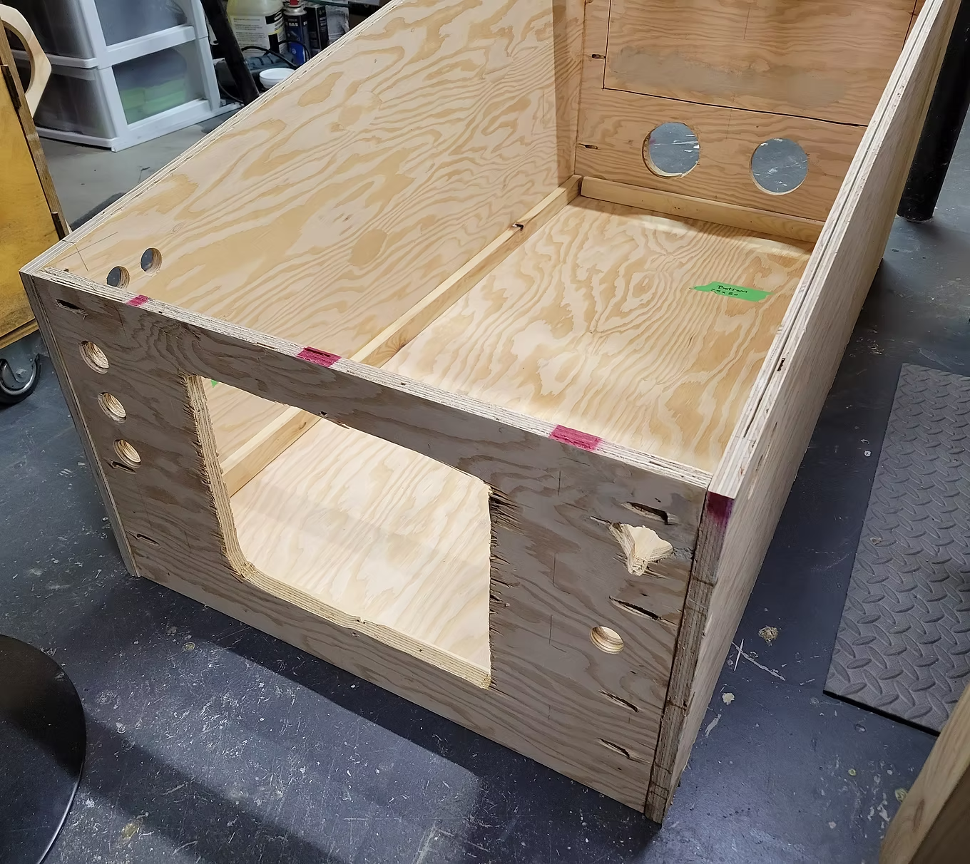
Drilling Button Holes
Mark the centre with a hole puncher. Drill slightly with a 1-3/8" bit, use painter tape to mark depth, then drill through with a 1" bit.
Mark the centre with a hole puncher. Drill slightly with a 1-3/8" bit, use painter tape to mark depth, then drill through with a 1" bit.
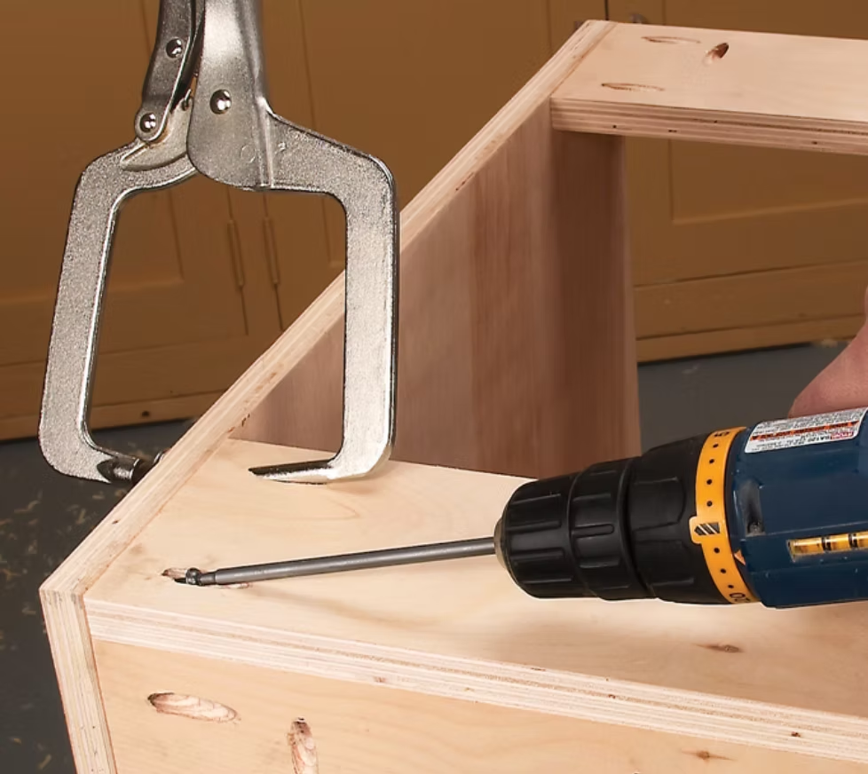
Assembly Tip
I used a Kreg pocket hole jig. Pocket holes hide screws and secure panels firmly — great for cabinet assembly.
I used a Kreg pocket hole jig. Pocket holes hide screws and secure panels firmly — great for cabinet assembly.
Gluing and Brad Nails
I used Titebond wood glue and brad nails to align panels, then screwed them in place using pocket holes.
I used Titebond wood glue and brad nails to align panels, then screwed them in place using pocket holes.
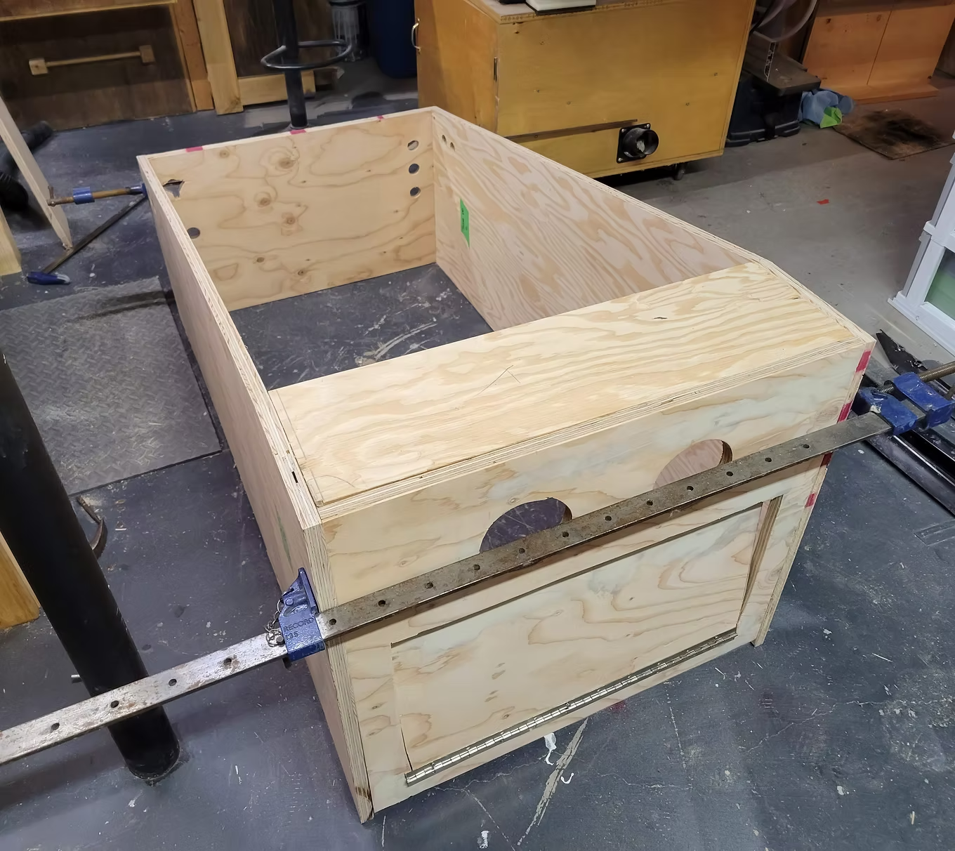
Front Panel
Cut the access door panel using a jigsaw. I drilled 3 holes on the left (Start, Extra Ball, Exit) and 1 on the right for ball launch. A hole was also cut for the plunger.
Cut the access door panel using a jigsaw. I drilled 3 holes on the left (Start, Extra Ball, Exit) and 1 on the right for ball launch. A hole was also cut for the plunger.
Backbox
Once all parts are cut per the plans, assembly is straightforward using pocket holes, brad nails, and glue.
Once all parts are cut per the plans, assembly is straightforward using pocket holes, brad nails, and glue.
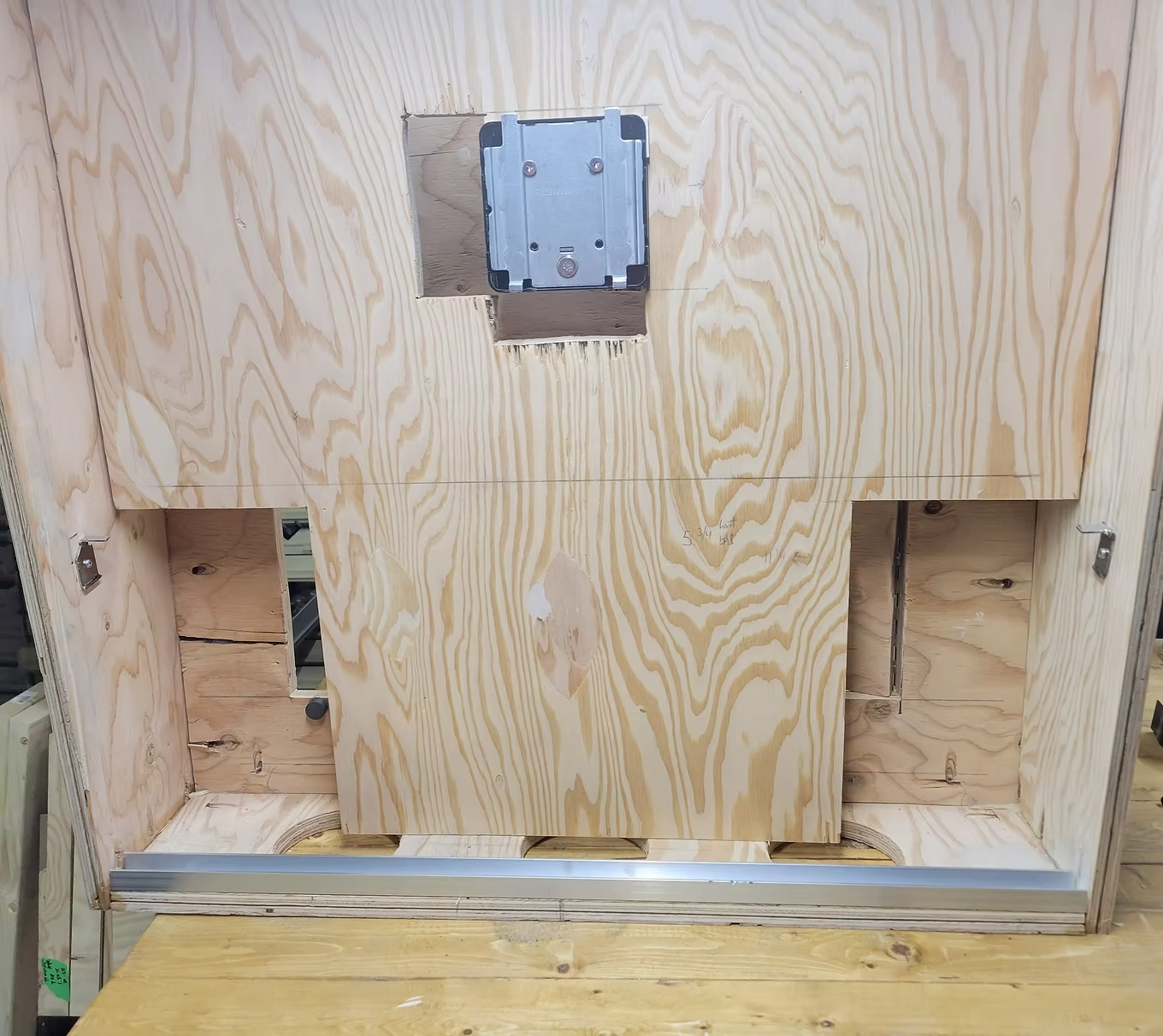
Backbox Monitor
I got a monitor with a detachable VESA mount, drilled it onto the wooden panel. The monitor clips on and is 100% secured.
I got a monitor with a detachable VESA mount, drilled it onto the wooden panel. The monitor clips on and is 100% secured.
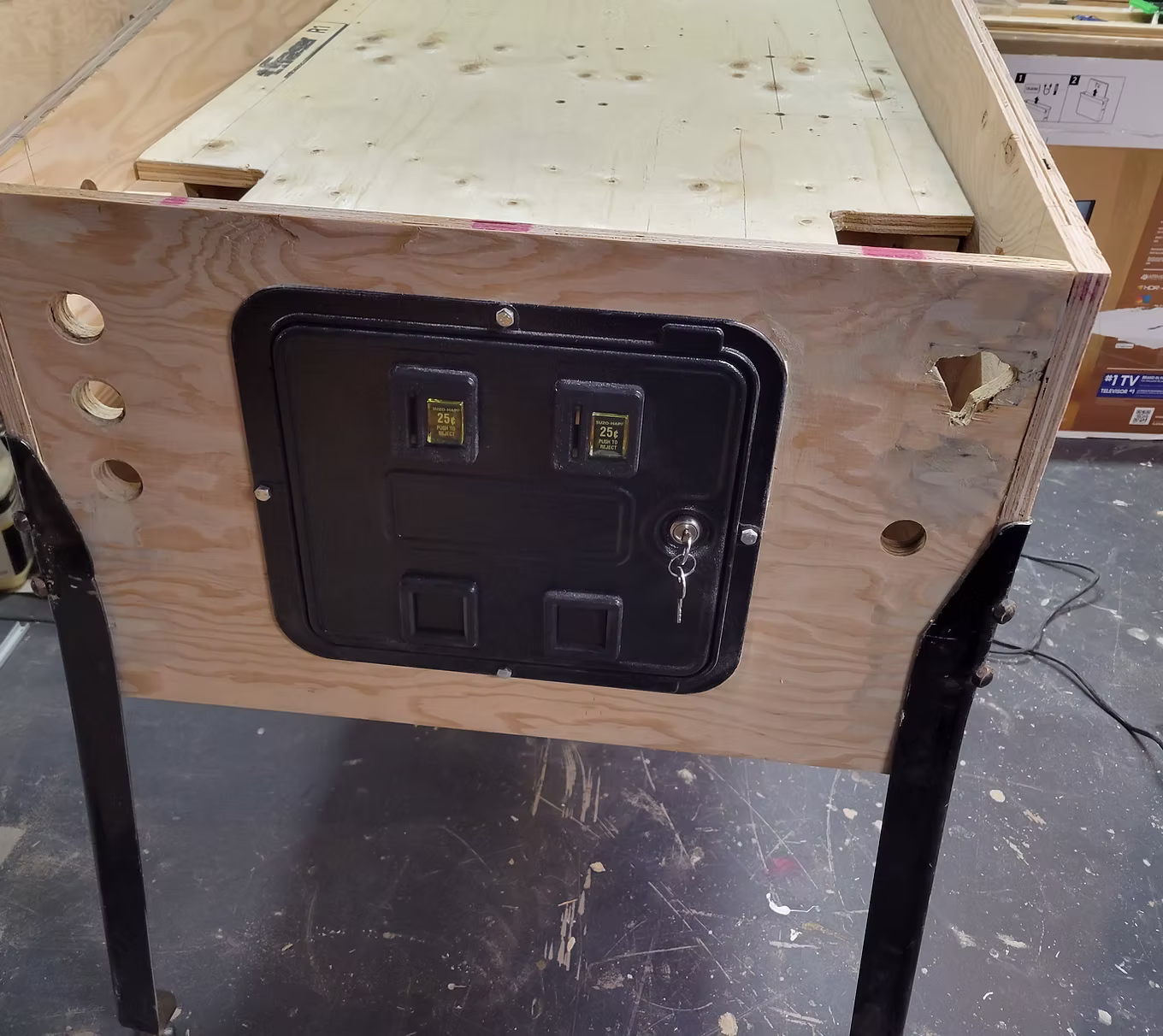
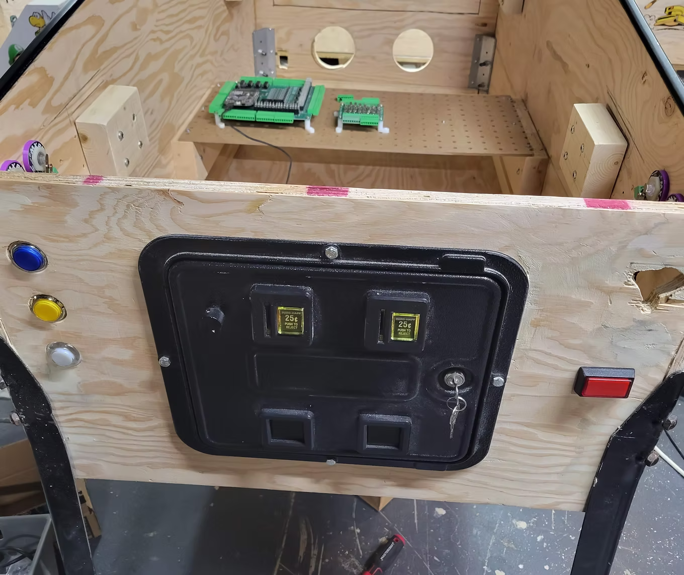
Installing the Service Door
The service door is secured to the cabinet using 4 bolts.
The service door is secured to the cabinet using 4 bolts.
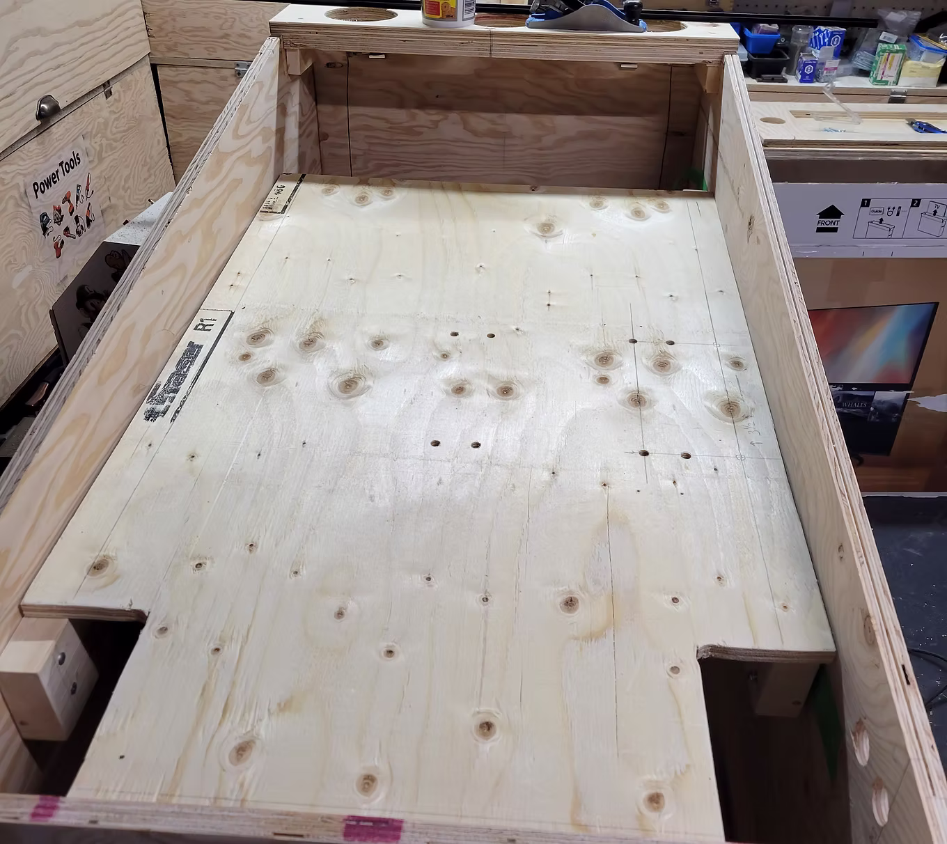
Playfield Monitor Support Lift
I cut a piece of wood the width of the inside of the cabinet (leaving ~1/8" each side) and cut an area around the flippers.
I cut a piece of wood the width of the inside of the cabinet (leaving ~1/8" each side) and cut an area around the flippers.
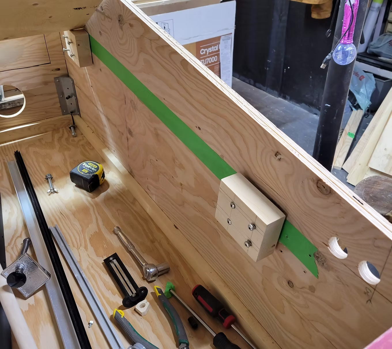
Monitor Support Blocks
Two small blocks of wood at the right inclination, screwed in place. Painter tape helps with alignment.
Two small blocks of wood at the right inclination, screwed in place. Painter tape helps with alignment.
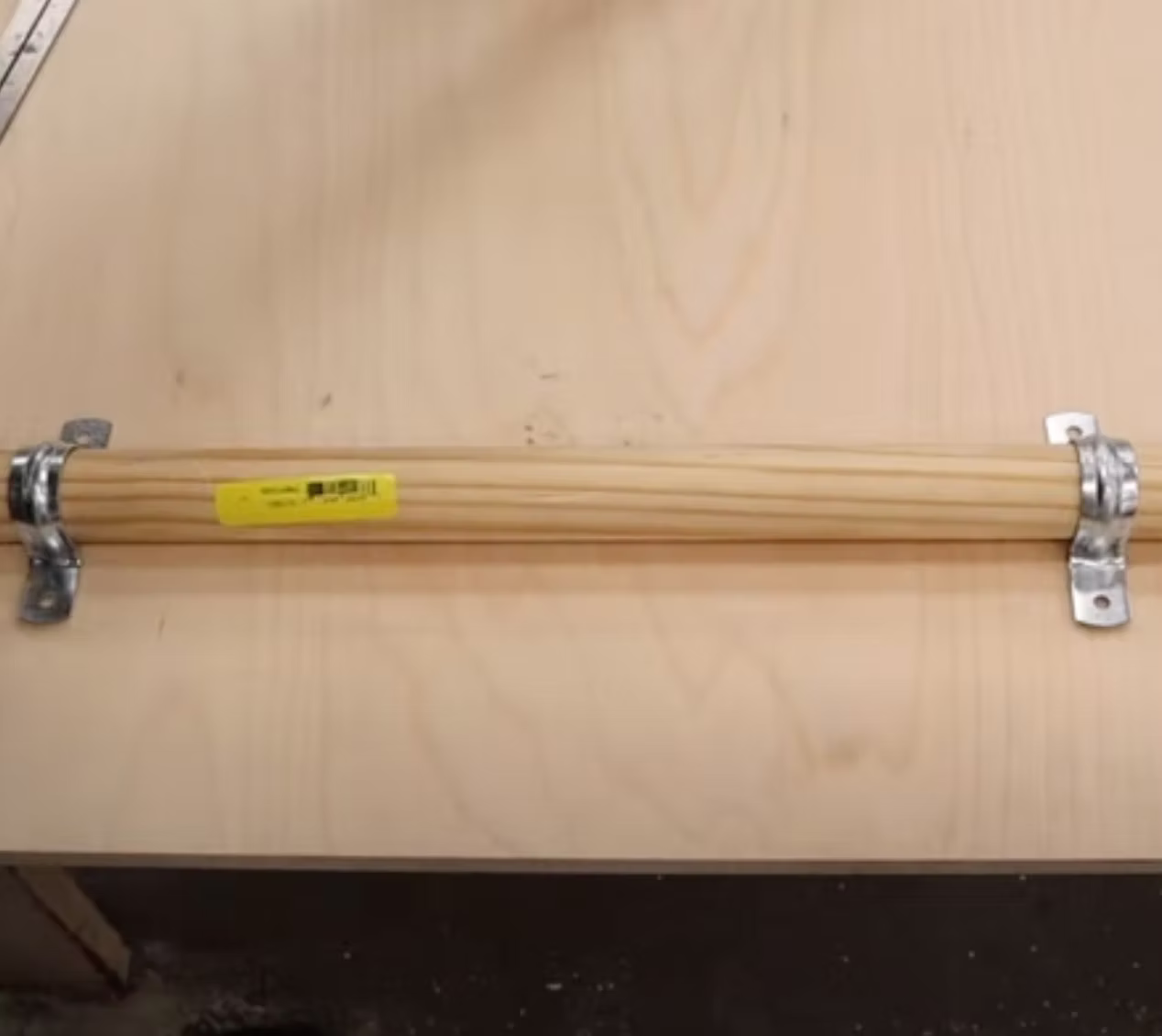
Monitor Support Lift Hinge
Using a 1" dowel strapped to the monitor support board with pipe strap clamps — the dowel sits in a U-shaped cut in the support block. This lets you lift the monitor for servicing.
Using a 1" dowel strapped to the monitor support board with pipe strap clamps — the dowel sits in a U-shaped cut in the support block. This lets you lift the monitor for servicing.
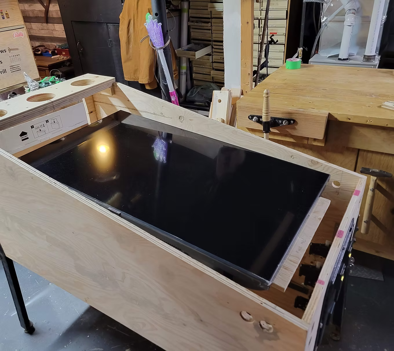
Mounting Monitor on the Lift Board
Calculate VESA mount bolt distances and bolt them to the hinge board. My monitor has a 200x200 VESA mount. Always lift the board — not the monitor.
Calculate VESA mount bolt distances and bolt them to the hinge board. My monitor has a 200x200 VESA mount. Always lift the board — not the monitor.
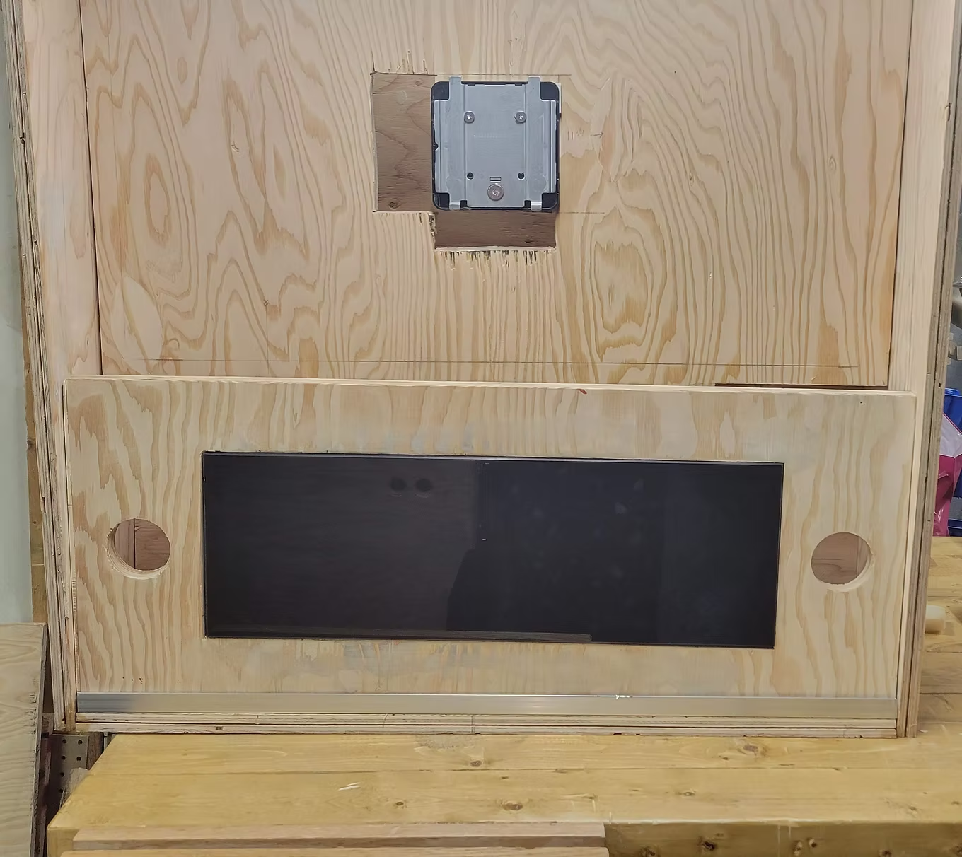
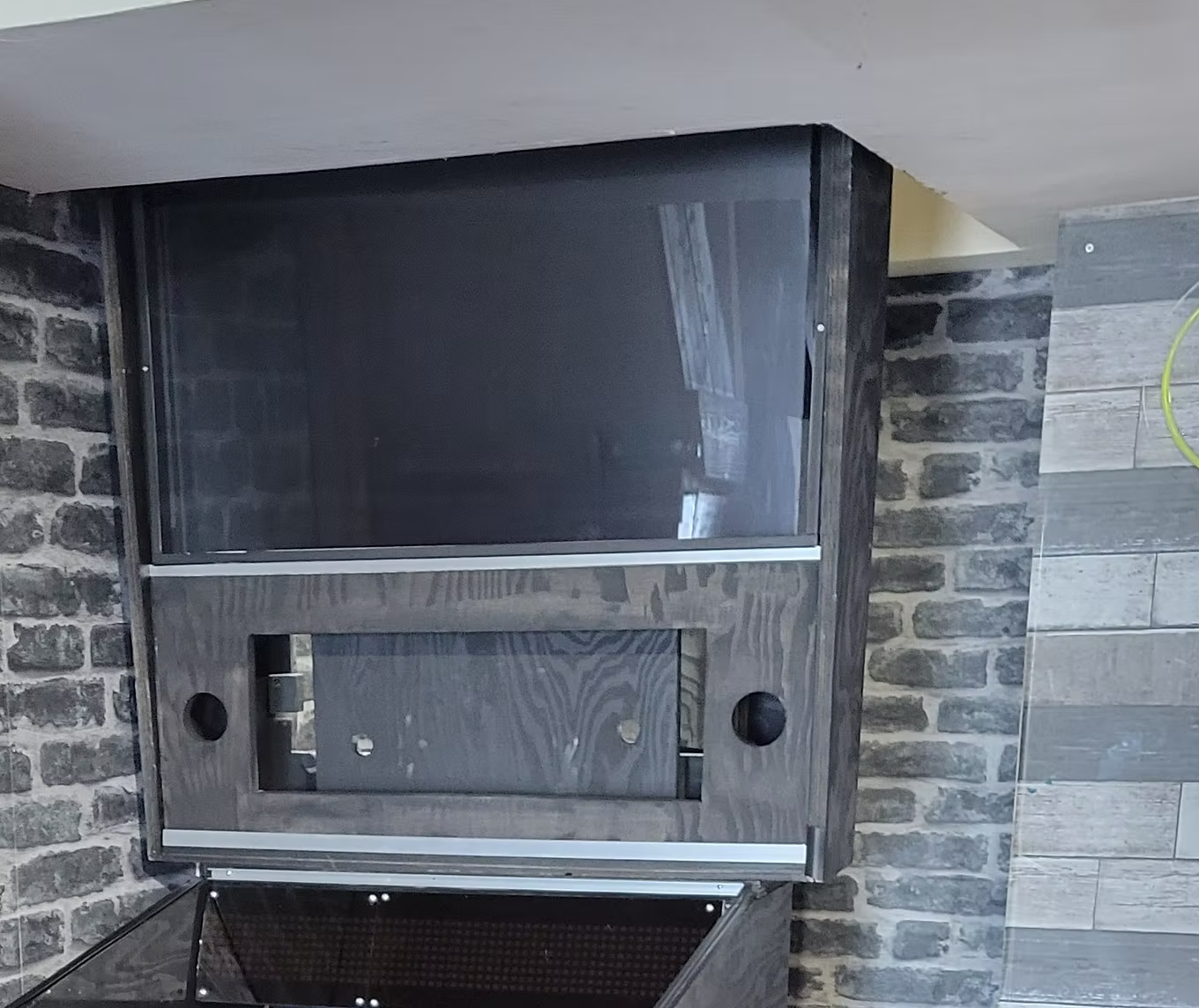
DMD Display
I switched to a Full DMD LCD setup which allows movies and animations. Originally I had cut an opening for a real DMD and two 3" speakers.
I switched to a Full DMD LCD setup which allows movies and animations. Originally I had cut an opening for a real DMD and two 3" speakers.
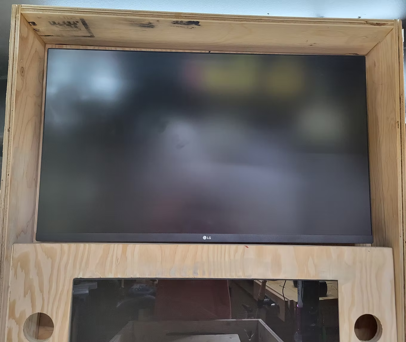
Mounting the Backglass Monitor
This is a 32" LG that clips onto the VESA mount. Good time to test the monitor lift board's durability — it supports at least 175 lbs!
This is a 32" LG that clips onto the VESA mount. Good time to test the monitor lift board's durability — it supports at least 175 lbs!
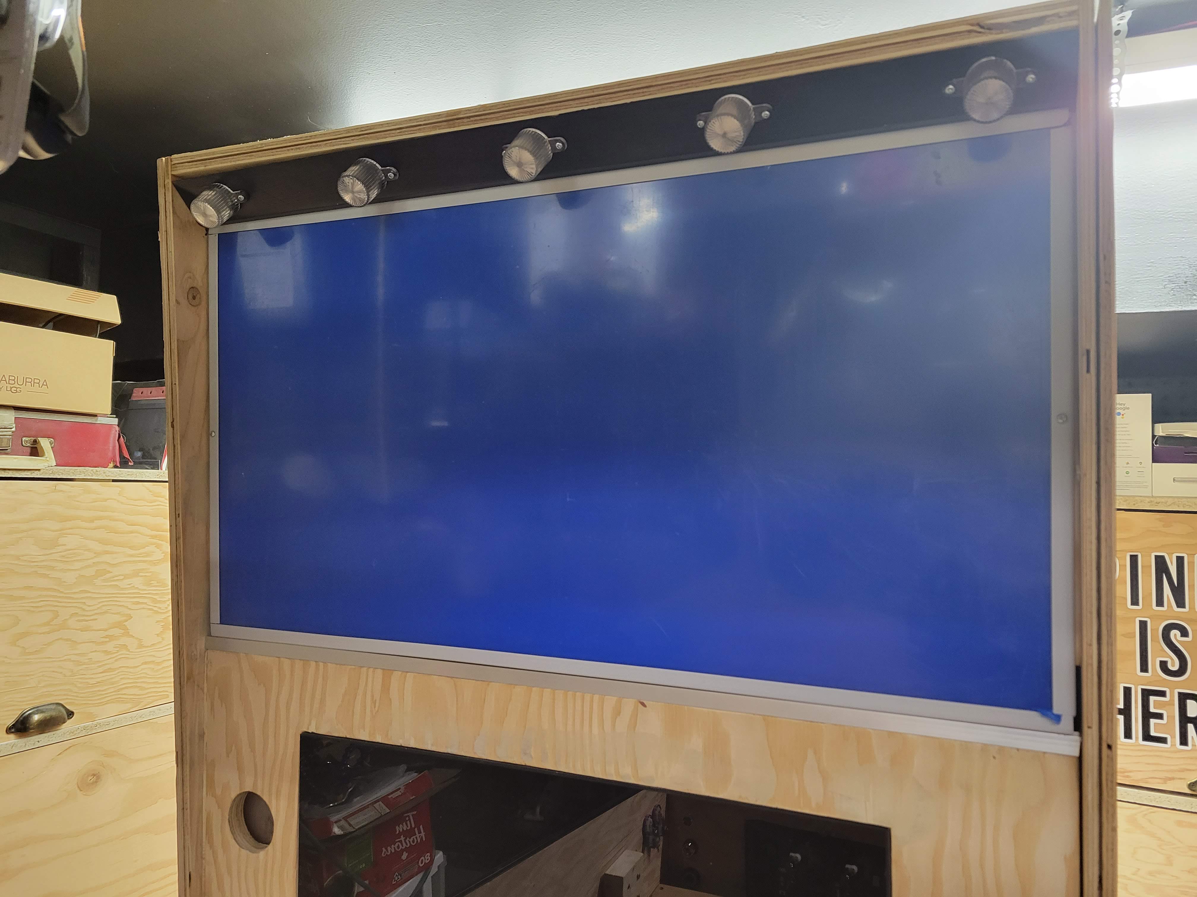
5 LED Flashbar
I cut a piece of wood the width of the backbox interior and spaced 5 RGB LEDs from Arnoz equally. A groove at the bottom lets the backglass plexiglass sheet slide in.
I cut a piece of wood the width of the backbox interior and spaced 5 RGB LEDs from Arnoz equally. A groove at the bottom lets the backglass plexiglass sheet slide in.
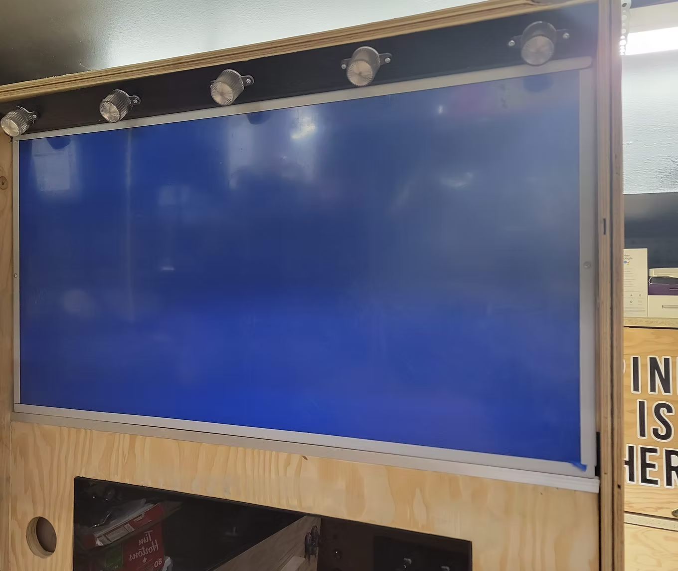
Flash Bar Mounting
All 5 LEDs wired from the back, secured by screwing from the top of the backbox.
All 5 LEDs wired from the back, secured by screwing from the top of the backbox.
Coat of Black Paint
I installed vinyl artwork so primed/painted first — vinyl adheres much better to a painted surface.
I installed vinyl artwork so primed/painted first — vinyl adheres much better to a painted surface.
Dry Fitting Buttons
Don't underestimate the importance of dry fitting. Install all buttons and leaf switches to get a feel for placement.
Don't underestimate the importance of dry fitting. Install all buttons and leaf switches to get a feel for placement.
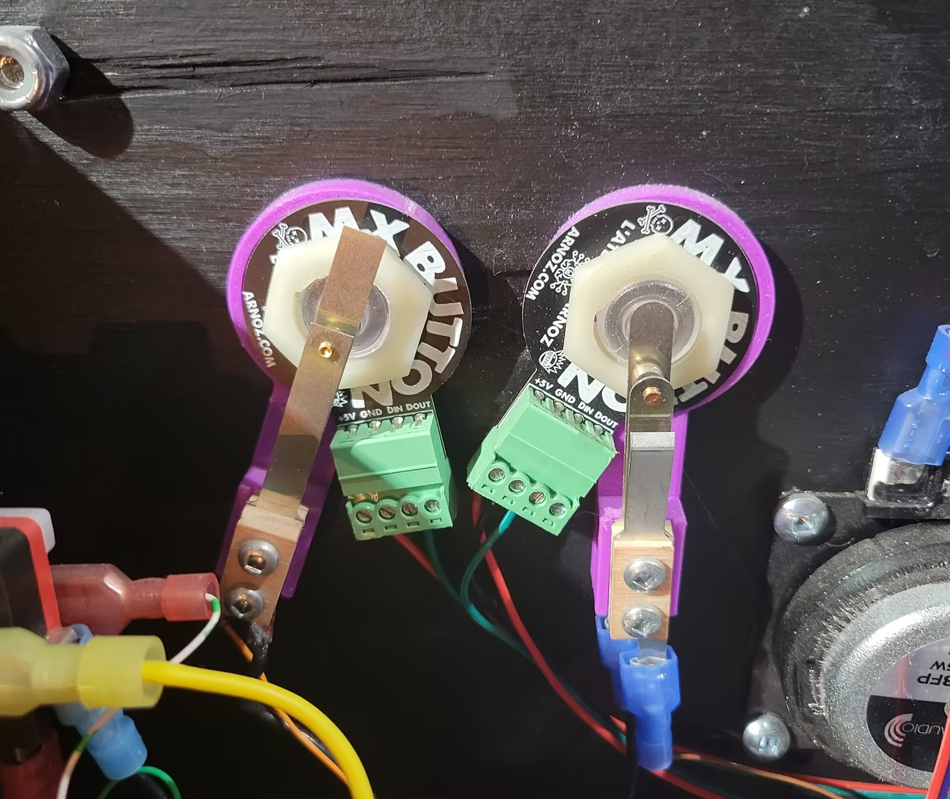
Connecting Buttons
I used the Arnoz Rigmaster — no tricky mapping or Joy2Key needed. Connect each button's ground to the Rigmaster ground and the signal to a button input.
I used the Arnoz Rigmaster — no tricky mapping or Joy2Key needed. Connect each button's ground to the Rigmaster ground and the signal to a button input.
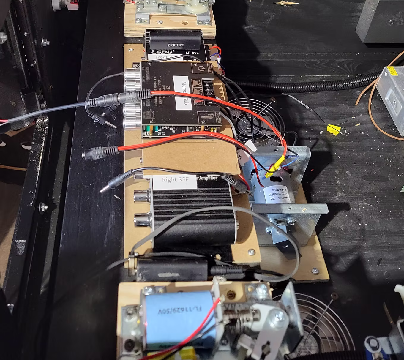
Installing SSF Exciters
I installed 4 × 25W exciters (2 front, 2 back) connected to two 2.1 audio amplifiers. SSF Tutorial →
I installed 4 × 25W exciters (2 front, 2 back) connected to two 2.1 audio amplifiers. SSF Tutorial →
Installing Flippers
I used a real pinball flipper assembly connected to a 24V power supply with a 1N4007 diode and 2A fuse. Very loud and satisfying. Force Feedback section →
I used a real pinball flipper assembly connected to a 24V power supply with a 1N4007 diode and 2A fuse. Very loud and satisfying. Force Feedback section →
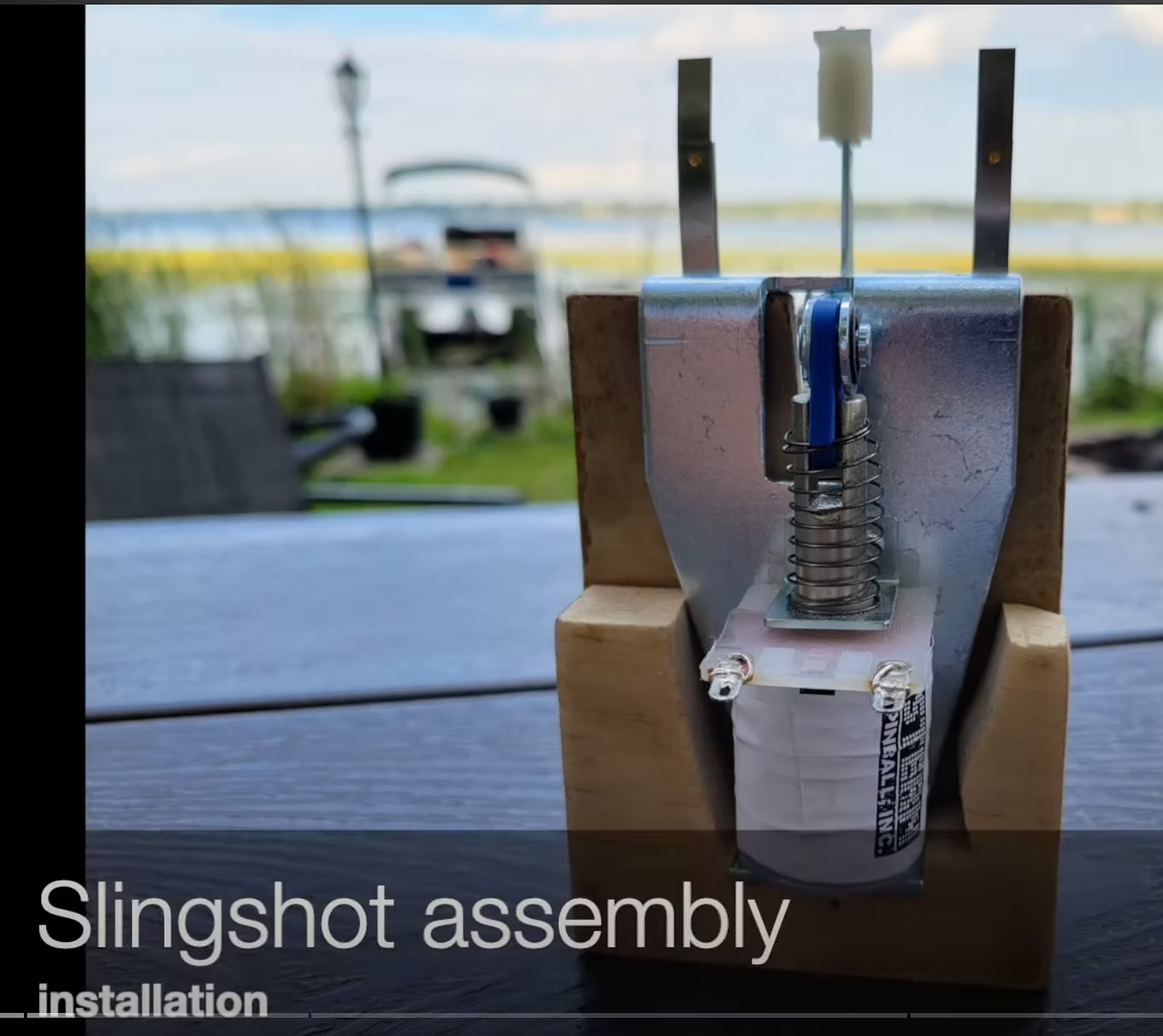
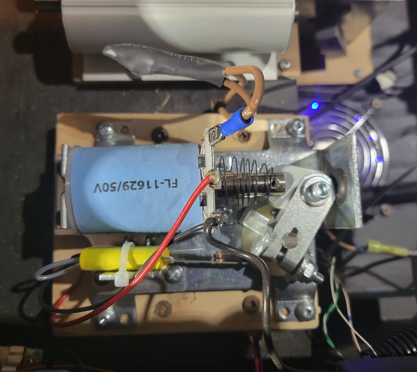
Installing the Slingshot
Real pinball slingshots installed below each flipper, connected to 24V with a diode and 2A fuse. I made a custom mounting bracket — watch the video.
Real pinball slingshots installed below each flipper, connected to 24V with a diode and 2A fuse. I made a custom mounting bracket — watch the video.
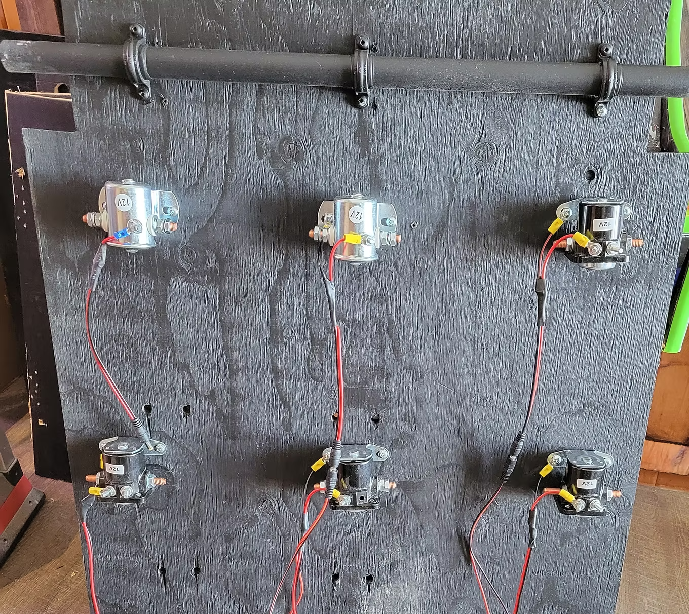
Bumper Solenoids
Installed solenoids for bumpers on the underside of the playfield monitor support lift — 3 at the back and 3 in the center.
Installed solenoids for bumpers on the underside of the playfield monitor support lift — 3 at the back and 3 in the center.
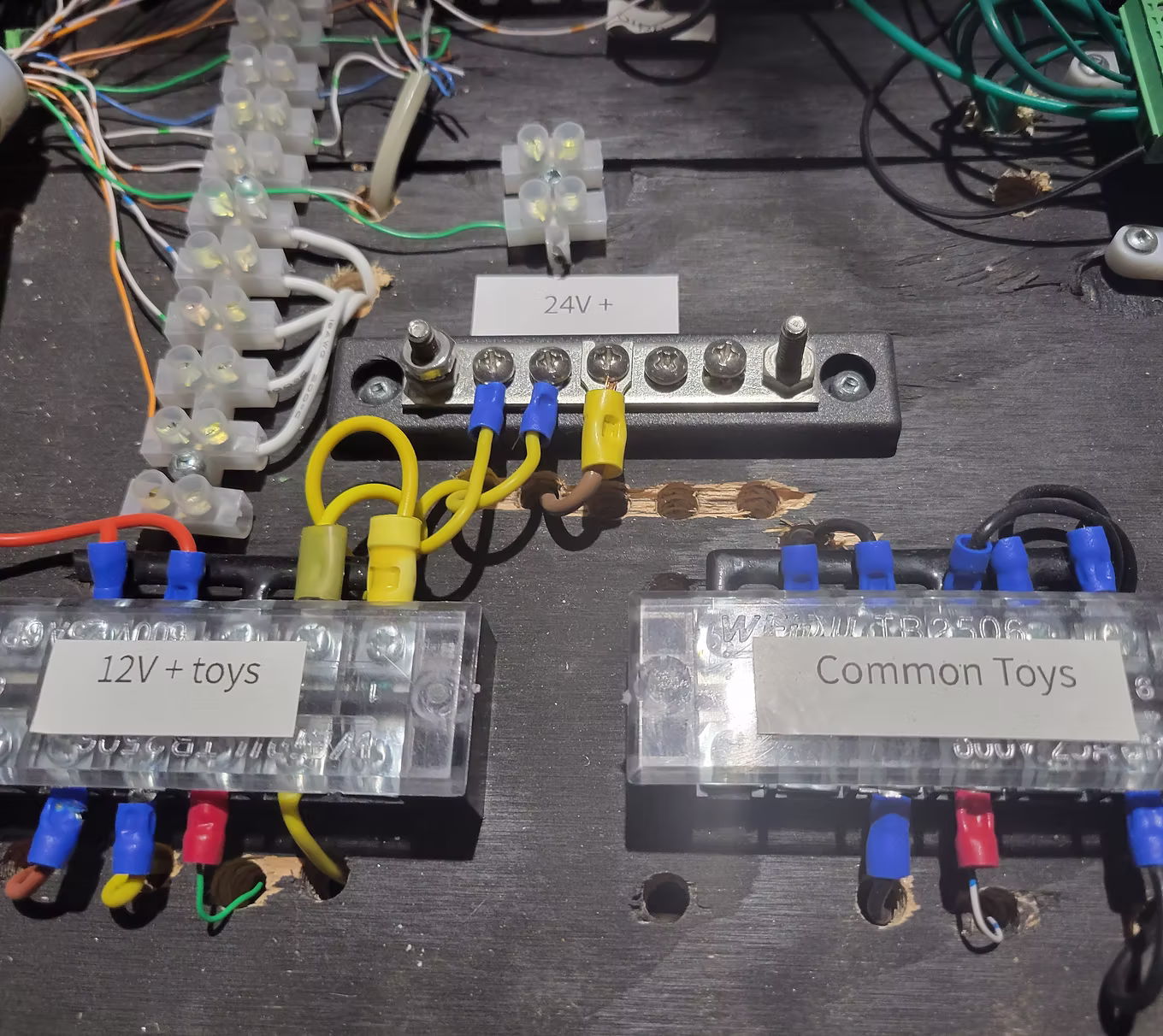
Wiring
Use a terminal block per voltage plus one for common ground. Color code: Black=ground, Blue=5V, Red=12V, Yellow=24V. Label everything. Watch the wiring video →
Use a terminal block per voltage plus one for common ground. Color code: Black=ground, Blue=5V, Red=12V, Yellow=24V. Label everything. Watch the wiring video →
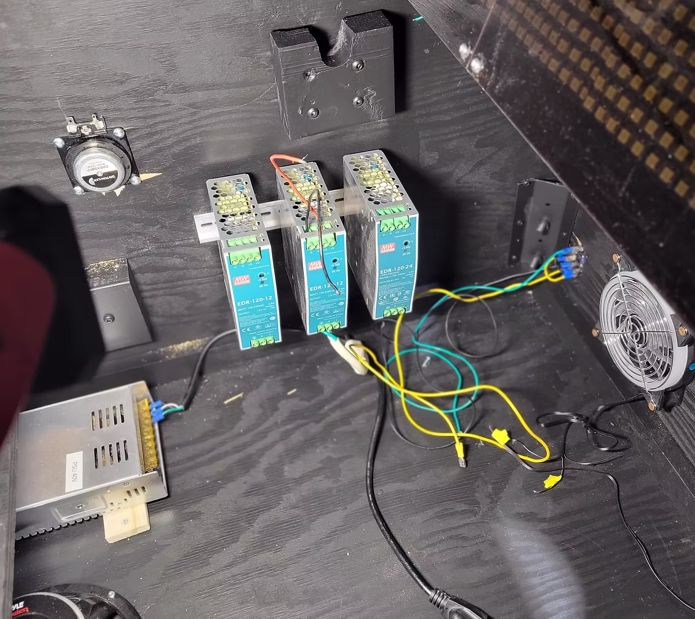
Power Supplies
Go big and you won't worry about future upgrades. Recommended: 5V/10A, 5V/60A (if addressable LED), 12V/15A, 24V/10A (if using 24V toys).
Go big and you won't worry about future upgrades. Recommended: 5V/10A, 5V/60A (if addressable LED), 12V/15A, 24V/10A (if using 24V toys).
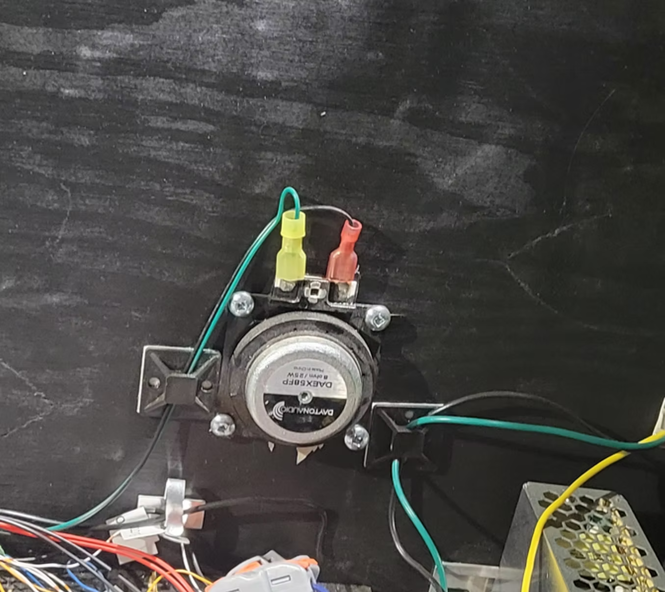
Installing the Shaker Motor
Mounted near the front of the cabinet on a wooden base screwed to the cabinet bottom.
Mounted near the front of the cabinet on a wooden base screwed to the cabinet bottom.
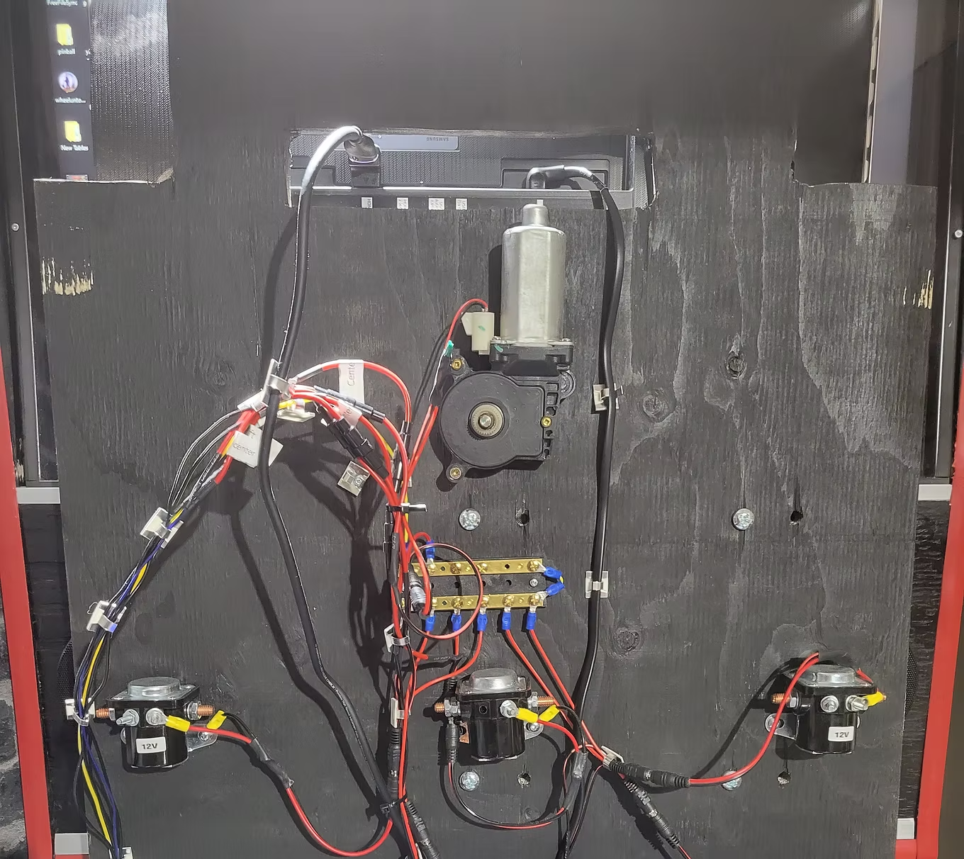
Installing the Gear Motor
An electric window motor mounted at the bottom of the playfield support lift. Uses a 2A inline fuse and 1N4007 diode.
An electric window motor mounted at the bottom of the playfield support lift. Uses a 2A inline fuse and 1N4007 diode.
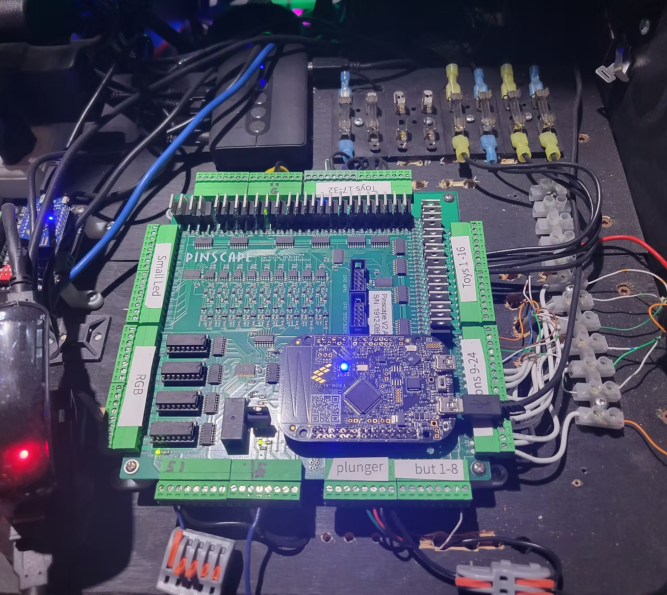
Installing the Pinball Controller
I used the Oak Micro All-in-One Pinscape board (now discontinued). See the Toys section for current alternatives. Connection guide available here (PDF).
I used the Oak Micro All-in-One Pinscape board (now discontinued). See the Toys section for current alternatives. Connection guide available here (PDF).