

Cab building
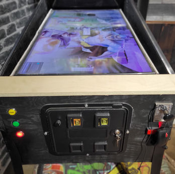
I built a full size virtual pinball cabinet and will share my steps. Shout out to Way of the wrench, i followed his buildiong guide and adapted it to my needs.
Way of the wrench cabinet plans and tutorial. I made my build based on his plans.

Get your wood
I used 3/4 birch plywood good one side, which will be very sturdy. The one good side plywood is more expensive but will save you time on the filling and sanding.

Marking and cutting
Take extra time to mark your lines and use a guide to ensure accuracy. Cutting your boards on a piece of styrofoam works like a charm.

Mark your pieces
I used painter tape to mark the dimensions and what they are. This will make it very easy when comes assembly time.

Dry fitting
It is a lot easier to make any adjustments in the dry fitting stage.

Back cabinet panel
I installed a piano hinge and drilled 2 4" holes where i am going to install my exhaust fans.

Back box vent holes
There will not be a lot of heat coming out of the backbox, simple holes at the top will be sufficient. I drilled using a 1 /18 Forstner bit.


Drilling buttons holes
Mark the centre of your button with a hole puncher and drill just a little bit with a 1 3/8" bit . You can use painter tape on your bit to indicate the dept. using a 1" bit then drill through the wood.


Assembling tip
I used a Craig pocket hole jig to drill pocket holes. Pocket holes are great for assembling a cabinet as it hides the screw and secures the panels firmly.


Gluing and brad nails
I used Titebond wood glue and brad nails to align the panels and they are screwed in place using pocket holes.


Front Panel
Cut the access door panel door according to the size of yours using a Jigsaw. I drilled 3 holes on the left side ( Start, Extra ball and exit ) and 1 on the right for the ball launch. A hole was also cut on the right side for the plunger.


Backbox
Once the parts are all cut to size as provided in the plans, assembly is very simple using pocket holes, brad nails and glue.


Backbox monitor
I was lucky enough to get a monitor with a detachable Vesa mount. i drilled the vesa mount on the wooden monitor piece. The monitor then clips on it and is 100% secured.


Installing the service door
Installing the service door is done by securing it to the cabinet using 4 bolts.


Playfield monitor support lift
I cut a piece of wood that will support the monitor. The piece is the width of the inside of the cabinet leaving about 1/8" on each side. I cut an area around the flippers.


Monitor support blocks
I used 2 small blocks of wood and verified that it has the inclination i wanted and screwer them in place. I used painter tape to help align the blocks.


Monitor support Lift hinge
Way of the wrench showed this technique to lift up your monitor for servicing the parts. This is a must , imagine having to remove your playfield every time you need to adjust something.Using a 1" dowel , you will strap it on the monitor support lift board using pipe strap clamps.
The Dowel will sit in a U shaped cut in the support block.


Mounting monitor on the lift hinge board
Calculating the distance of your Vesa mount bolts you will bolt them to the hinge board which will secure the monitor.
When testing the lift,
DO NOT lift by the monitor, always lift the board. My monitor has a 200x200 vesa mount.


DMD
I now switched to a Full DMD setup, which allows movie and animation to be played on the LCD. This was my original designed and i had cut an opening for a real DMD and two 3" speakers. This design was a Atgames Bitbixel HV Real DMD.


Mounting the backglass monitor
This is a 32" LG . It clipped on the Vesa mount attached to the panel as shown previously. This is a good time to test the durability of the Monitor support lift board as you can see me kneeling on it. Success it supports at least 175 Lbs.


5 LED Flashbar
I cut a piece of wood the width of the inside of the backbox. I then spaced out equally 5 RGB Led from Arnoz. The Groove in the bottom is to make the Backglass Plexyglass sheet slide in.


Flash bar mounting
I wired all 5 LED from the back and secured the LED bar by screwing from the top of the backbox


Coat of black paint
I will be installing Vinyl artwork but priming or painting is recommended as vinyl will adhere better to a painted surface.


Dry Fitting buttons
Do not underestimate the importance of dry fitting. Installing all your buttons and leaf switch will give you a good idea of the


Connecting buttons
I used Arnoz Rigmaster and this takes care of the buttons connection. No need for Tricky mapping or Joy2key. Connect the ground of each button to the Rigmaster buttons ground and connect the signal button to a button input
Installing the SSF exciters


I installed 4 25W exciters, 2 at the front and 2 at the back. They are connected to two 2.1 audio amplifiers.
Installing flippers


I used a real pinball flipper assembly. This produces a very loud clicking noice which is perfect for flippers. This connects to a 24v Power supply and i installed a 1N4007 diode and a 2 Amp fuse.
Installing the slingshot


The Slingshot are the big triangle rubber parts on each side of the drain.
They are used in a pinball table to bounce off the ball when it hits it.
I installed them just bellow the left and right flippers. I used a real pinball slingshot and makes some loud excellent noise. It is connected to the 24v Power supply. I also used a diode and a 2 Amp fuse. I also made a custom part that allows me to mount and secure the slingshot to the cabinet. You can watch a video where i am talking about it.
Bumpers Solenoids


Installing the solenoids for the bumpers on the bottom side of the playfield monitor support lift. i installed 3 at the back and 3 in the center.
Wiring


This is a very if not the most important part of your build. Taking simple steps will help you get the proper setup. I made several videos on the topic, you might want to watch them. I have a terminal block for each voltage and 1 for the common ground. Color coding your voltages will help you spot them much faster when troubleshooting. Labeling your wires will also be super helpful when troubleshooting.
Black = ground
blue = 5v
red = 12v
yellow = 24v
Electrical


Don't overthink choosing which power supply to use. Go big and you will not have to worry about any future upgrade of hardware addition. For a regular cabinet with most toys you will need those.
5V 10A
5V 60A ( If you have adressable LED )
12V 15A
24V 10A ( if you have anything on 24V )
Installing the shaker motor


I installed the shaker near the front of the cabinet. I mounted the shaker on a wooden base and screwed the base to the bottom of the cabinet.
Installing the Pinball controller


I have a few different virtual pinball controller, but this is my favourite. The Oak micro All in one Pinscape boards. Unfortunately , this board is no longer available for sale. You will find a list of alternatives in the Virtual Pinball hardware section. This board takes all my toys , led, plunger and buttons and i can configure the Pinscape software. It uses a KL25Z board and runs off 5 and 12v . I also made a video and guide on how to connect everything to it. It is available here for download.
Wiring


This is a very if not the most important part of your build. Taking simple steps will help you get the proper setup. I made several videos on the topic, you might want to watch them. I have a terminal block for each voltage and 1 for the common ground. Color coding your voltages will help you spot them much faster when troubleshooting. Labeling your wires will also be super helpful when troubleshooting.
Black = ground
blue = 5v
red = 12v
yellow = 24v
BUILDING CUSTOM WOOD LOCKBAR
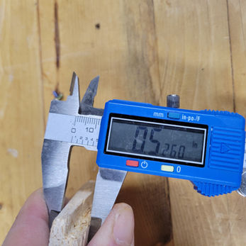
I made an executive desision to make the cab wider than a standard wide body. A wide body is typically 23.5 " this one is 26.5. Two reasons, number one this was what was in the plans i was following. Number 2, my previous experience with cabs, i always had issues making the screen fit. In this wide cab, a 43" monitors fits with enough room to spare without having to remove the monitor bezel.
The Issue i was facing was that a standard wide body lock bar is not going to fit. I do not own any metal bending machines so my only other option was to make it from wood.
I described each step in the pictures below. Clicking on the picture will give you additional information about the picture.


I I made this small desktop version of a router table. It has a small palm router upside down.


It looks pretty good and the grip is also comfortable.


